ITEM #0857432 12 AMP ROUTER WITH ROUTER TABLE MODEL #K11RTA-03 Español p. 41 ATTACH YOUR RECEIPT HERE Serial Number Purchase Date Questions, problems, missing parts? Before returning to your retailer, call our customer service department at 1-888-3KOBALT (1-888-356-2258), 8 a.m. - 8 p.m., EST, Monday - Friday.
TABLE OF CONTENTS Product Specifications....................................................................................... 3 Package Contents............................................................................................. 4 Safety Information.............................................................................................6 Preparation...................................................................................................... 12 Tools Needed............................
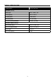
PRODUCT SPECIFICATIONS COMPONENT SPECIFICATION ROUTER (1311.3) Rated input 120V~, 60Hz, 12A Collet capacity 1/4 in. & 1/2 in. No-load speed 25,000 RPM Base dimension 6 in. (15.2 cm) Sub-base opening diameter 1-1/4 in. (3.1 cm) ROUTER TABLE (1034.2) Table switch rating 120 V~, 60 Hz, 15A Table size (approximate) 26.5 in. x 15-1/8 in, Table height 12-1/2 in. Max. load capacity 50 lbs.
PACKAGE CONTENTS NOTICE: To simplify handling and to minimize any damage that may occur during shipping, the router table comes partially assembled. Separate all the parts from the packaging materials and check each part against the package contents list in order to ensure that all parts have been included. Do this before discarding any of the packaging material. Carefully inspect the items to ensure that no breakage or damage has occurred during shipping.
PART NO. PARTS FOR ROUTER TABLE al DESCRIPTION QUANTITY Starter pin 1 am Tabletop insert with 1-1/4 in. diameter hole 1 an Tabletop insert with 1-7/8 in. diameter hole 1 ao Tabletop insert with 2-1/8 in. diameter hole 1 ap ‘Z’ Wrench 1 aq Double ended wrench 1 Router part list PART NO. PARTS FOR ROUTER DESCRIPTION QUANTITY ar Router 1 as Dust collection port with vacuum adaptor and 2 screws 1 at Chip guard (pre-installed on the router) 1 au 1/4 in.
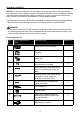
SAFETY INFORMATION Please read and understand this entire manual before attempting to assemble or operate this product. If you have any questions regarding the product, please call customer service at 1-888-3KOBALT, 8 a.m. - 8 p.m., EST, Monday - Friday. WARNING • The operation of any power tool can result in foreign objects being thrown into your eyes, which can result in severe eye damage.
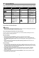
SAFETY INFORMATION Some of the following symbols may be used on this tool. Please study them and their meaning. Proper interpretation of these symbols will allow you to operate the tool better and more safely.
SAFETY INFORMATION • Do not abuse the cord. Never use the cord for carrying, pulling or unplugging the power tool. Keep cord away from heat, oil, sharp edges or moving parts. Damaged or entangled cords increase the risk of electric shock. • When operating a power tool outdoors, use an extension cord suitable for outdoor use. Use of a cord suitable for outdoor use reduces the risk of electric shock.
SAFETY INFORMATION Service • Have your power tool serviced by a qualified repair person using only identical replacement parts. This will ensure that the safety of the power tool is maintained. Specific Safety Warnings for Electric Router • Hold power tool by insulated gripping surfaces, because the cutter may contact its own cord. Cutting a “live” wire may make exposed metal parts of the power tool “live” and shock the operator.
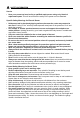
SAFETY INFORMATION Table 1: Recommended size of extension cords AMPERES RATING VOLTS TOTAL LENGTH OF CORD IN FEET 25 ft. 50 ft. 100 ft. 150 ft. AWG 0-6 6-10 120V~ 18 16 16 14 18 16 14 12 12 10-12 16 16 14 12-16 14 12 NOT RECOMMENDED • Wear proper apparel. Do not wear loose clothing, gloves, neckties, rings, bracelets, or other jewelry which may get caught in moving parts. Nonslip footwear is recommended. Wear protective hair covering to contain long hair. • Always use safety glasses.
SAFETY INFORMATION • Improper connection of the equipment-grounding conductor can result in a risk of electric shock. The conductor with insulation that has an outer surface that is green with or without yellow stripes is the equipment-grounding conductor. If repair or replacement is necessary, do not connect the equipment-grounding conductor to a live terminal.
PREPARATION Know Your Router and Router Table The fixed base router is designed to be used only for straight and grooved milling and the forming of edges in wood or similar materials. Any other uses of the router not described in this manual could damage the tool or seriously injure the operator and are, therefore, expressly excluded from approved applications. The router table has a precision-built electric switch box and it should only be connected to a 120V~ 60Hz power supply (normal household current).
PREPARATION PART DESCRIPTION PART DESCRIPTION A ON/OFF switch M Above-table depth adjustment nut B Motor housing N Motor clamp C Handle O Coarse-adjustment knob D Live-tool indicator P Edge-guide locking knobs E Fixed base Q Edge-guide mounting slots F Spindle-lock button R Vacuum adaptor G Collet/nut S In-feed fence H Sub-base T Out-feed fence I Chip guard U Feather boards J Replaceable brush cap V Miter gauge K Micro-fine adjustment dial W Integrated safety s
ASSEMBLY INSTRUCTIONS FOR ROUTER ASSEMBLING THE ROUTER AND BASE WARNING • ALWAYS turn the motor off and unplug the router from the power source before making any adjustments or installing accessories. Failure to turn the motor off and unplug the router could result in accidental starting, which can cause serious personal injury. 1. Removing/Installing the Router Base To Remove the Router Base a. b. c. d. Use the ON/OFF switch (A) to turn the motor off. Unplug the tool from the power source.
ASSEMBLY INSTRUCTIONS FOR ROUTER 2. Installing the Cutter Bit 2c Selecting a Cutter Bit (sold separately) F This router comes with 1/4 in. and 1/2 in. collets that accept cutter bits with 1/4 in. and 1/2 in. diameter shanks, respectively. G WARNING • Do not use router cutter bits that have a cutter bit diameter larger than 1-1/4 in., because they will not fit through the sub-base opening, could cause damage to the sub-base and the motor, and could cause serious personal injury to the operator. a. b.
ASSEMBLY INSTRUCTIONS FOR ROUTER ADJUSTING THE CUTTING DEPTH WARNING • Ensure that the router is never turned on or connected to the power source when assembling parts, making adjustments, or installing or removing collets and cutter bits, during cleaning, or when it is not in use. • Disconnecting the router will prevent accidental start-ups, which could cause serious personal injury. • The fixed base is designed with an adjustment system.
ASSEMBLY INSTRUCTIONS FOR ROUTER 5. To Adjust the Cutting Depth a. b. c. d. e. f. g. Place the router assembly on a flat, level surface, with the back of the fixed base (B) facing the operator. Loosen the motor clamp (N). With the cutter bit already installed, press the coarse-adjustment knob (O) and lower the motor into the base until the cutter bit is very close to the flat surface on which the base is sitting.
OPERATING INSTRUCTIONS FOR ROUTER WARNING • Before operating the router, follow all safety instructions in this manual. Failure to do so could result in serious personal injury. 6. ON/OFF Switch a. b. To turn the router ON, push the ON/OFF switch (A) to the “I” for “ON”. To turn it OFF, push the ON/OFF switch to the “O” for “OFF”. 6 A Always hold the router and cutter bit away from the workpiece when turning the switch “ON”.
OPERATING INSTRUCTIONS FOR ROUTER 8. Live-tool Indicator The live-tool indicator light (D) is located on the motor housing top cap where the power cord enters the motor housing (B). This green light is always on when the router motor is plugged into a power source. 8 D 9. Heavy-duty Edge Guide The edge guide can be used to aid in routing applications such as decorative edging, straightedge planing and trimming, grooving, dadoing and slotting.
OPERATING INSTRUCTIONS FOR ROUTER 11. Chip Guard 11 WARNING • The chip guard helps to keep dust and chips away from the operator. It will not stop objects larger than woodchips that are thrown from the bit. The chip guard is not intended as a safety guard. ALWAYS wear eye protection. • ALWAYS have the chip guard in place on the base when operating the router. To remove the chip guard (I) from the fixed base (E), press inward on its tabs until the chip guard releases from the fixed base, then remove it.
OPERATING INSTRUCTIONS FOR ROUTER NOTICE: Arbor-type bits with pilots are excellent for shaping the edge of any workpiece that is either straight or curved, if the curvature is at least as great as the radius of the bit to be used. WARNING • Always clamp the workpiece securely and keep a firm grip on the router base with both hands at all times. Failure to do so could result in loss of control, causing possible serious personal injury.
OPERATING INSTRUCTIONS FOR ROUTER 14. Freehand Routing 14 WARNING • Do not use large cutter bits for freehand routing. The use of large cutter bits when freehand routing could cause loss of control or create other hazardous conditions that could result in personal injury. When used freehand, the router becomes a flexible and versatile tool. This flexibility makes it possible to easily rout signs, relief sculptures, etc. When freehand routing: a. b. c. Draw or lay out the pattern on the workpiece.
OPERATING INSTRUCTIONS FOR ROUTER FEEDING THE ROUTER The key to professional routing results is to set-up for the cut carefully, selecting the proper cutting depth, knowing how the cutter bit reacts in the workpiece, and selecting the appropriate rate and direction of feed for the router. 15. Direction of Feed for External Cuts If the router is fed in the opposite direction (right to left), the rotating force of the cutter bit will tend to push the bit away from the workpiece.
OPERATING INSTRUCTIONS FOR ROUTER 16. Direction of Feed for Internal Cuts When making an internal cut, such as a groove, dado or slot, always position the guide (edge guide, straight edge, or board guide) so that it will be on the right-hand side of the router as the cut is made. a. When the guide is positioned on the right-hand side of the router, the router travel is from left to right, and “counterclockwise” around curves.
OPERATING INSTRUCTIONS FOR ROUTER Rate of Feed The proper rate of feed depends on several factors: the hardness and moisture content of the workpiece, the cutting depth, and the cutting diameter of the bit. Use a faster rate of feed when cutting shallow grooves in soft woods, such as pine. Use a slower rate of feed when making deep cuts in hardwoods, such as oak. 17.
ASSEMBLY INSTRUCTIONS FOR ROUTER TABLE 19. Attaching the Switch Box to the Table a. b. c. d. Insert a nut (ad) into the slot on the switch box. Align the holes on the switch box with the holes on the router table. Hold the switch with one hand and hold the nut in place with one finger. Insert the pan-head screw (ad) into the hole and tighten it with the double ended wrench (aq). Repeat with the other screw.
ASSEMBLY INSTRUCTIONS FOR ROUTER TABLE 20. Attaching the Legs to the Tabletop a. b. c. d. e. f. g. h. Place the router table surface assembly on a flat, level surface, with the underside of the table facing up. Position a leg against the underside of the tabletop surface as shown. Align the two slots on the router table surface assembly with the holes in the leg bracket. Place a spring washer and a small washer onto each of the two short hexagon socket screws (af).
ASSEMBLY INSTRUCTIONS FOR ROUTER TABLE 21. Attaching the Router to the Table a. b. c. d. e. Unplug the router and the router table. Remove the three pan-head screws on the sub-base (H) to remove it from the router. Place the router upside down so that it is resting on its top cap and align the hole (3) with the above-table depth adjustment nut (M) located on the router. Align the three holes (1) in the center of the router table surface with the holes in the router.
ASSEMBLY INSTRUCTIONS FOR ROUTER TABLE 22. Installing Tabletop Insert 22 WARNING • Always unplug the router table before attaching accessories or making any adjustment. ao an am This router table includes three tabletop inserts, each with an opening of different diameter: insert with 1-1/4 in. diameter opening (am), insert with 1-7/8 in. diameter opening (an), and an insert with 2-1/8 in. diameter opening (ao). Select a table top insert with a clearance hole that W is 3/4 in.
ASSEMBLY INSTRUCTIONS FOR ROUTER TABLE 23. Attaching the Fence Assembly to the Table 23 WARNING • Always unplug the router table before attaching accessories or making any adjustment. a. b. c. d. e. The fence is shipped completely assembled; loosen the three bolts and clamping knobs before attaching it to the table. Place the fence assembly on the tabletop surface and align the three holes on the bottom of the fence assembly with the slots on the router table.
ASSEMBLY INSTRUCTIONS FOR ROUTER TABLE 25. Attaching the Feather Boards 25 U WARNING • Always unplug the router table before attaching accessories or making any adjustment. NOTICE: The front and back side of each feather board is marked to indicate the proper feed direction. Attach the feather board to the fence a. b. c. Place the feather board (U) on the fence assembly as shown. Insert two round-head, square-neck bolts through the two holes in the fence and the slots in the feather board.
ASSEMBLY INSTRUCTIONS FOR ROUTER TABLE ABOVE-TABLE DEPTH ADJUSTMENT 27. To Adjust the Cutting Depth 27 WARNING • Always unplug the router table before attaching accessories or making any adjustment. The router table features an access hole (3) to permit above-the-table router depth adjustment. a. b. c. Loosen the motor clamp (N) on the router. Insert the “Z” wrench through the adjusting hole and into the depth adjustment nut in the router, then turn the wrench to move the router collet down or up.
OPERATING INSTRUCTIONS FOR THE ROUTER TABLE When using the router installed in the table, use the following instructions. 28. Switch Box Operation Two receptacles are located at the back of the integrated safety switch (W). Use one for plugging in the router. The other may be used to plug in a vacuum or a light (not included). 28a WARNING • To ensure safety and reliability, when one receptacle is used for the router, the capacity of the other receptacle is limited to 3 A.
OPERATING INSTRUCTIONS FOR THE ROUTER TABLE 29. Using a Vacuum The vacuum adaptor in the fence assembly is 2-1/4 in. diameter. Select the vacuum accordingly. NOTICE: Operating the router table without a vacuum can result in an excessive build-up of sawdust and wood chips under the fence assembly and guard and in the cabinet, reducing the performance of the router table and fence assembly.
OPERATING INSTRUCTIONS FOR THE ROUTER TABLE ROUTING WITH THE FENCE The fence supports and guides the workpiece. To provide the best support during routing operations, the fence facings should be as close to the bit as possible without contacting the bit (typically, about 1/4 in. from the bit is a suitable distance). 30 30. Adjusting the Fence Forward and Backward a. b. c. Loosen the three clamping knobs. Move the fence assembly forward or backward along the slots to the desired position.
OPERATING INSTRUCTIONS FOR THE ROUTER TABLE 33. Routing with Feather Boards Feather boards (U) are helpful for controlling the workpiece while routing, and they assist in keeping the workpiece flat on the tabletop and snug to the fence The tabletop feather board, combined with the fence feather board, help to keep the workpiece pressed against the fence and tabletop. The best location for the feather boards varies according to your application, workpiece size, and other factors. a. b. c. d. e.
CARE AND MAINTENANCE General WARNING • All maintenance should only be carried out by an authorized service organization. Cleaning WARNING • Before cleaning or performing any maintenance, make sure that the router and the router table have been disconnected from the power supply. Keep all ventilation openings clean to prevent overheating of the motor. Wear a mask and proper eye protection when you clean the tool with compressed air.
CARE AND MAINTENANCE 35. Replacing Carbon Brushes a. b. c. d. Unplug the router motor before inspecting or replacing brushes. Replace both carbon brushes when either has less than 1/4 in. of carbon remaining, or if the spring or wire is damaged or burned. Use a slotted screwdriver (not included) to remove the black plastic cap (J) on each side of the router motor. Carefully remove the spring-loaded brush assemblies. Keep brushes clean and sliding freely in their guide channels.
TROUBLESHOOTING WARNING • Place the switch to “OFF” position and unplug the router and table before performing troubleshooting procedures. PROBLEM The router does not work POSSIBLE CAUSE CORRECTIVE ACTION The switch on the router is in the “OFF” position. Turn the switch to “ON” position. The switch on the router table is in the “OFF” position. Insert the key and pull the switch to the “ON” position The carbon brushes have worn out.
ARTÍCULO #0857432 REBAJADORA DE 12 AMP CON MESA PARA REBAJADORA MODELO #K11RTA-03 ADJUNTE SU RECIBO AQUÍ Número de serie Fecha de compra ¿Preguntas, problemas, piezas faltantes? Antes de volver a la tienda, llame a nuestro Departamento de Servicio al Cliente al 1-888-3KOBALT (1-888-356-2258), de lunes a viernes de 8 a.m. a 8 p.m., hora estándar del Este.
ÍNDICE Especificaciones del producto......................................................................... 43 Contenido del paquete.................................................................................... 44 Información de seguridad................................................................................ 46 Preparación..................................................................................................... 53 Herramientas necesarias...........................................
ESPECIFICACIONES DEL PRODUCTO COMPONENTE ESPECIFICACIONES REBAJADORA (1311.3) Consumo nominal 120 V~, 60 Hz, 12 A Capacidad de la boquilla de sujeción 1/4 pulg. y 1/2 pulg. Velocidad sin carga 25.000 RPM Dimensión de la base 6 pulg. (15,2 cm) Diámetro de abertura de la subbase 1-1/4 pulg.. (3.1 cm) MESA PARA REBAJADORA (1034.2) Clasificación del interruptor de la mesa 120 V~, 60 Hz, 15 A Tamaño de la mesa (aproximado) 26,5 pulg. x 15-1/8 pulg. Altura de la mesa 12-1/2 pulg.
CONTENIDO DEL PAQUETE AVISO: La mesa para rebajadora viene parcialmente ensamblada para simplificar la manipulación y minimizar cualquier daño que pueda ocurrir durante el transporte. Separe todas las piezas del material de empaque y compare cada pieza con la lista de contenido del paquete para asegurarse de que todas las piezas se hayan incluido. Haga lo siguientes antes de desechar el material de embalaje.
PIEZA N.° PIEZAS PARA MESA PARA REBAJADORA ak DESCRIPCIÓN CANTIDAD Ensamble del indicador de inglete 1 Pasador de inicio 1 am Encarte de la superficie de la mesa con un orificio de 3,17 cm de diámetro 1 an Encarte de la superficie de la mesa con un orificio de 4,76 cm de diámetro 1 ao Encarte de la superficie de la mesa con un orificio de 5,39 cm de diámetro 1 ap Llave inglesa "Z" 1 aq Llave inglesa doble 1 al Lista de piezas de la mesa para rebajadora PIEZA N.
INFORMACIÓN DE SEGURIDAD Lea y comprenda completamente este manual antes de intentar ensamblar u operar este producto. Si tiene preguntas relacionadas con el producto, llame al Departamento de Servicio al Cliente al 1-888-3KOBALT, de lunes a viernes de 8 a. m. a 8 p. m., hora estándar del Este. ADVERTENCIA • Durante el funcionamiento de cualquier herramienta eléctrica, pueden entrar objetos extraños a los ojos y causar graves daños oculares.
INFORMACIÓN DE SEGURIDAD Algunos de los siguientes símbolos pueden aparecer en esta herramienta. Obsérvelos y aprenda su significado. La interpretación correcta de estos símbolos le permitirá utilizar la herramienta de manera eficaz y segura.
INFORMACIÓN DE SEGURIDAD • Evite el contacto del cuerpo con superficies conectadas a tierra, como tuberías, radiadores, extractores o refrigeradores. Existe un mayor riesgo de descarga eléctrica si su cuerpo tiene puesta a tierra. • No exponga las herramientas eléctricas a la lluvia o a condiciones de humedad. Si ingresa agua en una herramienta eléctrica, aumentará el riesgo de descarga eléctrica. • No maltrate el cable. Nunca use el cable para transportar, jalar ni desenchufar la herramienta eléctrica.
INFORMACIÓN DE SEGURIDAD • Desconecte el enchufe de la fuente de alimentación o la batería de la herramienta eléctrica antes de realizar cualquier ajuste, cambiar accesorios o almacenar herramientas eléctricas. Este tipo de medidas de seguridad preventivas reduce el riesgo de arranques accidentales de la herramienta eléctrica.
INFORMACIÓN DE SEGURIDAD • Siempre use brocas de corte diseñadas para esta rebajadora. Nunca use brocas de corte más grandes de diámetro que la abertura, ya que esto podría ocasionar una posible pérdida de control o crear otras condiciones peligrosas que podrían causar lesiones personales graves. Advertencia de seguridad general para herramientas para banco • Mantenga los protectores en su lugar y en buenas condiciones de funcionamiento. • Retire las llaves de ajuste o las llaves inglesas.
INFORMACIÓN DE SEGURIDAD • No se extienda demasiado. Mantenga una postura y un equilibrio adecuados en todo momento. • Realice un mantenimiento adecuado de las herramientas. Mantenga las herramientas limpias y afiladas para obtener el rendimiento más óptimo y más seguro. Siga las instrucciones para lubricar y reemplazar accesorios. • Desconecte las herramientas antes de realizar el mantenimiento o al cambiar sus accesorios, como las hojas de corte, las brocas, los cortadores y similares.
INFORMACIÓN DE SEGURIDAD • Esta herramienta está diseñada para su uso en un circuito que tenga un tomacorriente (esquema B). La herramienta tiene un enchufe de puesta a tierra (esquema A). Se puede usar un adaptador temporal (esquemas D) para conectar este enchufe a un tomacorriente de 2 polos (esquema C), si un electricista calificado no instaló un tomacorriente con una puesta a tierra adecuada.
PREPARACIÓN Conozca su rebajadora y mesa para rebajadora La rebajadora de base fija está diseñada para usarse solo para fresados rectos o ranurados, y para crear bordes en madera u otros materiales similares. Cualquier otro uso de la rebajadora no descrito en este manual podría dañar la herramienta o lesionar gravemente al operador, por lo que están expresamente excluidos de las aplicaciones aprobadas.
PREPARACIÓN PIEZA DESCRIPCIÓN PIEZA DESCRIPCIÓN A Interruptor de encendido/ apagado (ON/OFF) M Tuerca de ajuste de profundidad de la mesa de arriba B Carcasa del motor N Abrazadera del motor N Abrazadera del motor C Manija O Perilla de ajuste grueso O Perilla de ajuste grueso D Indicador de herramienta activa P Perillas de fijación de la guía de borde P Perillas de fijación de la guía de borde E Base fija Q Ranuras de montaje de la guía de borde Q Ranuras de montaje de la guía de bord
INSTRUCCIONES DE ENSAMBLAJE DE LA REBAJADORA ENSAMBLAJE DE LA REBAJADORA Y LA BASE ADVERTENCIA • SIEMPRE apague el motor y desenchufe la rebajadora de la fuente de alimentación antes de realizar ajustes o instalar accesorios. Si no apaga el motor ni desenchufa la rebajadora, se puede producir un arranque accidental y causar lesiones personales graves. 1. Instalación o remoción la base de la rebajadora Para retirar la base de la rebajadora a.
INSTRUCCIONES DE ENSAMBLAJE DE LA REBAJADORA 2. Instalación de la broca de corte Selección de una broca de corte (se vende por separado) 2c F G Esta rebajadora viene con boquillas de sujeción de 1/4 pulg. y 1/2 pulg. que admiten brocas de corte con vástagos de un diámetro de 1/4 pulg. y 1/2 pulg., respectivamente. ADVERTENCIA • No use las brocas de corte para rebajadora que tienen un diámetro de broca de corte superior a 1-1/4 pulg.
INSTRUCCIONES DE ENSAMBLAJE DE LA REBAJADORA AVISO: • Para evitar daños a la herramienta, no apriete la boquilla de sujeción sin la broca de corte instalada. • Para asegurar un agarre correcto del vástago de la broca de corte y minimizar el desgaste, el vástago de la broca de corte debe insertarse al menos 5/8 pulg. (16 mm) en la boquilla de sujeción. • La boquilla de sujeción cuenta con autoliberación. NO es necesario golpear la boquilla de sujeción para liberar la broca de corte para rebajadora.
INSTRUCCIONES DE ENSAMBLAJE DE LA REBAJADORA Compruebe al girar la perilla de ajuste microfino (K) en dirección de las manecillas del reloj y en dirección contraria a las manecillas del reloj para confirmar que la broca sube y baja. En caso contrario, presione la perilla de ajuste grueso (O) y gire la perilla de ajuste microfino hasta que los engranajes enganchen y luego restablezca a cero “0” en el anillo indicador de profundidad (L).
INSTRUCCIONES DE FUNCIONAMIENTO DE LA REBAJADORA AVISO: Nunca se aconseja hacer un solo corte profundo. Las brocas de corte de diámetro más pequeño se rompen fácilmente con demasiada fuerza de torsión y empuje lateral. Las brocas de corte más grandes harán un corte áspero y será difícil guiar y controlar. Por estos motivos, no exceda los 3,17 mm de profundidad de corte en una sola pasada. Cortes profundos a. b. c. d. e.
INSTRUCCIONES DE FUNCIONAMIENTO DE LA REBAJADORA 7. Luces de trabajo led El motor de la rebajadora tiene 3 luces de trabajo incorporadas, que se encuentran alrededor de la boquilla de sujeción; estas iluminan el área de corte. Estas luces siempre están encendidas cuando el interruptor de encendido/apagado (ON/ OFF) (A) está en la posición de encendido. 7 8.
INSTRUCCIONES DE FUNCIONAMIENTO DE LA REBAJADORA 10. Recolección de polvo con adaptador para aspiradora 10 La rebajadora está equipada con un adaptador para aspiradora que admite un adaptador de manguera para aspiradora de 1-1/4 pulg. (3,2 cm) (no está incluido). Para fijar el adaptador a la base fija (E), colóquelo y sujételo a la parte posterior de la base con dos tornillos (incluidos). 11.
INSTRUCCIONES DE FUNCIONAMIENTO DE LA REBAJADORA AVISO: Hacer cortes de prueba es esencial con la mayoría de las aplicaciones de rebaje. Una prueba de corte genera información sobre la mejor configuración, la velocidad de la rebajadora y la profundidad del corte, además de cómo la broca de corte reacciona en la pieza de trabajo.
INSTRUCCIONES DE FUNCIONAMIENTO DE LA REBAJADORA 13. Rebajado interno a. b. c. d. e. 13 Una vez que la profundidad de corte está configurada, incline la rebajadora y colóquela en la pieza de trabajo, con solo el extremo principal de la subbase (H) en contacto con la pieza de trabajo. Encienda el motor y deje que el motor alcance la velocidad máxima, sea cuidadoso de no dejar que la broca de corte entre en contacto con la pieza de trabajo.
INSTRUCCIONES DE FUNCIONAMIENTO DE LA REBAJADORA AVISO: • Frecuentemente, se utiliza una caja de testigos o una broca de ranura en V para rebajar letras y grabar objetos. Las brocas rectas y los molinos de bolas se suelen utilizar para aliviar tallados. Las brocas de venas se utilizan para tallar detalles pequeños y elaborados. • Nunca se aconseja hacer un solo corte profundo. Las brocas de diámetro más pequeño se rompen fácilmente si se aplica demasiada fuerza de torsión y empuje lateral.
INSTRUCCIONES DE FUNCIONAMIENTO DE LA REBAJADORA Para proteger contra un contragolpe y evitarlo, planifique la configuración y la dirección de alimentación de manera que los bordes filosos de la broca de corte golpeen constantemente rectos contra la madera sin cortar. Además, siempre inspeccione la pieza de trabajo para detectar la presencia de nudos, vetas duras y objetos extraños que podrían causar un problema de retroceso. 16.
INSTRUCCIONES DE FUNCIONAMIENTO DE LA REBAJADORA 17. Alimentación demasiado rápida Los cortes terminados, limpios y lisos solamente se pueden alcanzar cuando la broca de corte rota a una velocidad relativamente alta, hace mordidas muy pequeñas y produce astillas pequeñas y de corte limpio. 17 Alimentación demasiado rápida Forzar la alimentación de la broca de corte hacia delante demasiado rápido reduce las RPM de la broca de corte y los cortes son más grandes a medida que rota.
INSTRUCCIONES DE ENSAMBLAJE DE LA MESA PARA REBAJADORA 19. Fijación de la caja del interruptor a la mesa a. b. c. d. Coloque una tuerca (ad) en la ranura de la caja del interruptor. Alinee los orificios de la caja del interruptor con los orificios de la mesa para rebajadora. Sostenga el interruptor con una mano y mantenga a la tuerca en su lugar con un dedo. Coloque el tornillo de cabeza plana (ad) en el orificio y apriételo con la llave inglesa doble (aq). Repita la operación con el otro tornillo.
INSTRUCCIONES DE ENSAMBLAJE DE LA MESA PARA REBAJADORA 20. Fijación de las patas a la superficie de la mesa a. b. c. d. e. f. g. h. Coloque el ensamble de la superficie de la mesa para rebajadora sobre una superficie plana y nivelada, con la parte inferior de la mesa hacia arriba. Coloque una pata contra la parte inferior de la superficie de la mesa como se muestra. Alinee las dos ranuras del ensamble de la superficie de la mesa para rebajadora con los orificios ubicados en la abrazadera de la pata.
INSTRUCCIONES DE ENSAMBLAJE DE LA MESA PARA REBAJADORA 21. Fijación de la rebajadora a la mesa a. Desenchufe la rebajadora y la mesa para rebajadora. b. Retire los tres tornillos de cabeza plana de la subbase (H) para retirarla de la rebajadora. c. Coloque la rebajadora boca abajo de manera que descanse sobre la tapa superior y alinee el orificio (3) con la tuerca de ajuste de profundidad de la mesa de arriba (M) ubicada en la rebajadora.
INSTRUCCIONES DE ENSAMBLAJE DE LA MESA PARA REBAJADORA 22. Instalación del encarte de la superficie de la mesa 22 ao an am ADVERTENCIA • Siempre desconecte la mesa para rebajadora antes de fijar accesorios o realizar cualquier ajuste. Esta mesa para rebajadora incluye tres encartes de la superficie de la mesa, cada uno con una abertura de diferente diámetro: encarte con una abertura de 1-1/4 pulg. de diámetro (am), encarte con una abertura de 1-7/8 pulg.
INSTRUCCIONES DE ENSAMBLAJE DE LA MESA PARA REBAJADORA 23. Fijación del ensamble de la guía a la mesa 23 ADVERTENCIA • Siempre desconecte la mesa para rebajadora antes de fijar accesorios o realizar cualquier ajuste. a. b. c. d. e. La guía se envía completamente ensamblada; desajuste los tres tornillos y las perillas de sujeción antes de fijarla a la mesa.
INSTRUCCIONES DE ENSAMBLAJE DE LA MESA PARA REBAJADORA 25. Fijación de las tablas con canto biselado 25 U ADVERTENCIA • Siempre desconecte la mesa para rebajadora antes de fijar accesorios o realizar cualquier ajuste. AVISO: El frente y la parte posterior de cada tabla con canto biselado están marcados para indicar la dirección de alimentación adecuada. Fije la tabla con canto biselado a la guía. a. b. c. Coloque la tabla con canto biselado (U) sobre el ensamble de la guía como se muestra.
INSTRUCCIONES DE ENSAMBLAJE DE LA MESA PARA REBAJADORA AJUSTE DE PROFUNDIDAD DE LA MESA DE ARRIBA 27. Para ajustar la profundidad de corte 27 ADVERTENCIA • Siempre desconecte la mesa para rebajadora antes de fijar accesorios o realizar cualquier ajuste. La mesa para rebajadora cuenta con un orificio de acceso (3) para permitir el ajuste de profundidad de la rebajadora para la mesa de arriba. a. b. c. Orificio 3 Afloje la abrazadera del motor (N) sobre la rebajadora.
INSTRUCCIONES DE FUNCIONAMIENTO DE LA MESA PARA REBAJADORA Cuando use la rebajadora instalada en la mesa, siga las instrucciones a continuación. 28a 28. Funcionamiento de la caja del interruptor Hay dos tomacorrientes ubicados en la parte posterior del interruptor de seguridad integrado (W). Utilice uno para enchufar la rebajadora. El otro se puede usar para enchufar una aspiradora o una lámpara (no incluidas).
INSTRUCCIONES DE FUNCIONAMIENTO DE LA MESA PARA REBAJADORA 29. Uso de una aspiradora El adaptador para aspiradora del ensamble de la guía tiene 5,71 cm de diámetro. Seleccione una aspiradora de acuerdo con ese diámetro. AVISO: Operar la mesa para rebajadora sin una aspiradora puede resultar en una acumulación excesiva de polvo y astillas de madera debajo del ensamble de la guía, en el protector y en el gabinete, lo cual reduce el rendimiento de la mesa para rebajadora y el ensamble de la guía.
INSTRUCCIONES DE FUNCIONAMIENTO DE LA MESA PARA REBAJADORA REBAJADO CON LA GUÍA La guía sostiene y dirige la pieza de trabajo. Para proporcionar el mejor soporte durante las operaciones de rebajado, la guía debe estar lo más cerca de la broca posible sin hacer contacto con la broca (por lo general, alrededor de 1/4 pulg de la broca es una distancia adecuada). 30 30. Ajuste de la guía hacia delante y hacia atrás a. b. c. Afloje las tres perillas de sujeción.
INSTRUCCIONES DE FUNCIONAMIENTO DE LA MESA PARA REBAJADORA 33. Rebajado con tablas con canto biselado Las tablas con canto biselado (U) son útiles para controlar la pieza de trabajo durante el rebajado y ayudan a mantener la pieza de trabajo de manera plana sobre la superficie de la mesa y ajustada a la guía. La tabla con canto biselado de la superficie de la mesa, junto con la tabla con canto biselado de la guía, ayudan a mantener la pieza de trabajo presionada contra la guía y la superficie de la mesa.
CUIDADO Y MANTENIMIENTO General ADVERTENCIA • Todas las tareas de mantenimiento deben realizarse por una organización de servicio autorizada. Limpieza ADVERTENCIA • Antes de limpiar o realizar cualquier mantenimiento, asegúrese de que la rebajadora y la mesa para rebajadora estén desconectadas del suministro de electricidad. Mantenga todas las aberturas de ventilación limpias para evitar sobrecalentar el motor.
CUIDADO Y MANTENIMIENTO Lubricación Todos los rodamientos en esta herramienta se lubrican con una cantidad suficiente de lubricante de alta calidad para que duren toda la vida útil de la herramienta en condiciones de operación normales. Por lo tanto, no se necesita más lubricación. 35. Reemplazo de cepillos de carbono 35 a. Desenchufe el motor de la rebajadora antes de J inspeccionar o reemplazar los cepillos. b.
SOLUCIÓN DE PROBLEMAS ADVERTENCIA • Coloque el interruptor en la posición “OFF” (apagado) y desconecte la rebajadora y la mesa antes de realizar procedimientos de solución de problemas. PROBLEMA La rebajadora no funciona. La superficie de la mesa no está plana. No se puede fijar la rebajadora a la mesa. CAUSA POSIBLE ACCIÓN CORRECTIVA El interruptor de la rebajadora está en la posición “OFF” (apagado). Coloque el interruptor en la posición “ON” (encendido).