
Installation Guide

2
ASSEMBLY INSTRUCTIONS
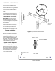
1. Remove the handle kit from the
cabinet. Attach the Door Handles (Fig-
ure 1.). Insert one Hole Plug into each
end of the Push Handle then attach
the handle to the end with the swivel
casters.
2. Thread the black lift knob into the
bottom of the slot in door centerpost.
3. WATCHMAN® III Lock System -
IMPORTANT: Carefully follow the
separate instructions (see inside of
door) which will guide you to a proper
lock installation.
4. Remove the tape from the swivel
casters. Using a mechanical lifting de-
vice, raise the cabinet slightly, then
knock the honeycomb blocks off of the
cabinet bottom using a rubber mallet.
Drawer Installation
Two types of drawer and drawer
slides are available for Models 55 &
57. The upper three positions will re-
ceive three 1" drawers or one 1" and
one 2-1/2" drawer, both with regular
duty slides. The six lower positions will
receive 2-1/2", 6", or 9-1/2" 12 gauge
drawers with heavy-duty slides.
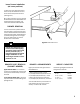
Upper Drawer Installation
(three upper positions)
Take one slide (Figure 2.) and insert
the clips (Inset) into the front and rear
notches of the drawer support panel.
Push the slide to the rear and down.
Secure slide with a screw through end
access hole in the slide.
#6 x 1/2"
Screw
Figure 2. Upper Drawer Slide Installation
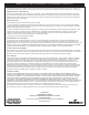
Figure 3. Installing Lower Drawers
FRONT VIEW
CABINET MEMBER
DRAWER MEMBER
CABINET MEMBER
SIDE VIEW
Rear
Front
RETENTION LUG