
User's Manual
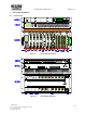
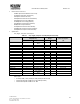
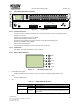
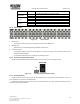
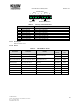
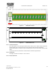
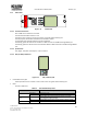
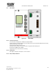
Table Of Contents
- User Manual
- For
- POD System
- Safety and Regualtion Warning Notice
- 1. POD System Overview
- 2. POD system Components
- 2.1 Head-end Unit
- 2.2 Remote Unit
- 3. Equipment Installation
- 4. Cable Connection
- 5. Specification

User Manual for POD Systems Revision: 0.7
© KMW USA Inc.
1818 E. Orangethrope Ave, Fullerton, CA 92831
Tel. +1 (714) 515-1100
www.kmwcomm.com
23
2.1.1 POD-H-DMCU (DAS Main Control Unit)
Figure 2-3 POD-H-DMCU
2.1.1.1 Functions and features
- Controls, monitors, and generates alarms for all connected modules and units in a POD DAS system
- Supports up to 4 racks.
- Supports up to 4 H-OIMs and up to 6 H-OEMs.
- Provides web-based GUI interface to user
- Provides the user interface to control and monitor using LCD window and key pad.
- Send alarms to O&M system by SNMP.
- Ethernet port forward function
- Provides external input/output ports for external alarm monitoring
2.1.1.2 Specifications
- Size, weight, and power consumption: refer to Table 2-1
2.1.1.3 LED, LCD & Key PAD, Reset
Figure 2-4 LED, LCD & Key PAD, Reset
LCD window and key pad
- H-DMCU provides the user interface to control and monitor using LCD window and key pad.
Reset
- Used for H-DMCU reset.
LED
Table 2-2 POD-H-DMCU LED Operation
Specifications
Run
Solid Green
When power is on.
OFF
When power is off.
Link
Solid Yellow
When H-DMCU cannot communicate with at least one module
among modules which are directly connected to H-DMCU such as H-
SCM or H-PSU.
ENT
Up
Down
ESC
Reset
Run
DMCU
Alarm
Link
HE
Alarm
RU
Alarm
1
2
3
4
5 7
6 8
9 11 13 15
10 12 14 16
17 19 21 23
18 20 22 24
25 27 29 31
26 28 30 32
Modem
Web GUI
KMW
HPSU
Power SW
DMCU
1 2 3
External Alarm
Input
Output
1 2 3 4
5 6 7 8
ENT
Up
Down
ESC
Reset
Run
DMCU
Alarm
Link
HE
Alarm
RU
Alarm