
User's Manual
Ste
p
1
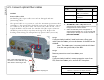
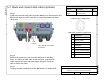
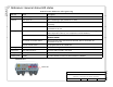
Required materials
Part No. Description Qty.*
Depends on
length
AISG connection cable, 8-
pin circular DIN
1
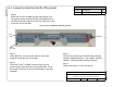
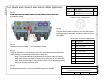
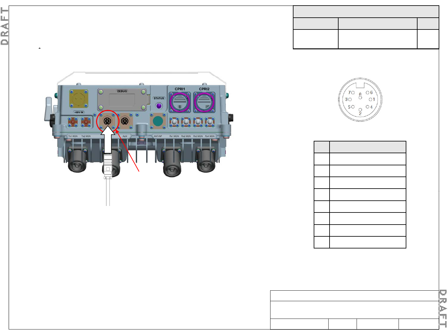
5-7. Route and connect AISG cable (optional)
p
Install and route the AISG cable from the AISG port on the bottom of the
RRH to the respective AISG controller or external antenna line device
(ALD) port.
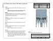
Connector pin configuration
AISG cable terminal configuration
AISG
(output)
Pin Designation
1 +12 V DC output
2 -48 V DC output
3 RS485 B
S 2
Note: AISG OUT ports have
female pins.
4 RS485 GND
5 RS485 A
6 +10 V to +30 V DC output
7 DC return
S
tep
2
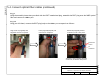
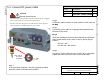
Remove the protective cover from the AISG port on the RRH.
Note: To connect an AISG cable to the AISG port, plug the AISG
cable into the AISG port and hand tighten the outer connector
shell to secure the cable.
8 N/C
Alcatel-Lucent RRH 2x60-B4
Alcatel-Lucent – Internal
Proprietary – Use pursuant to Company instruction
3MN-01520-0002-RJZZA Issue 0.02 March 2014
Sheet 20 of 24
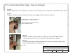
Step 3
Connect the AISG output port to the AISG IN port of another ALD.