
User's Manual
Step 1
Install and route the alarm cables from the alarm ports to the alarm
Required materials
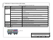
Part No. Description Qty.
Depends on
length
User alarm cable, 4 pair,
circular DIN male on one end
1 or
2
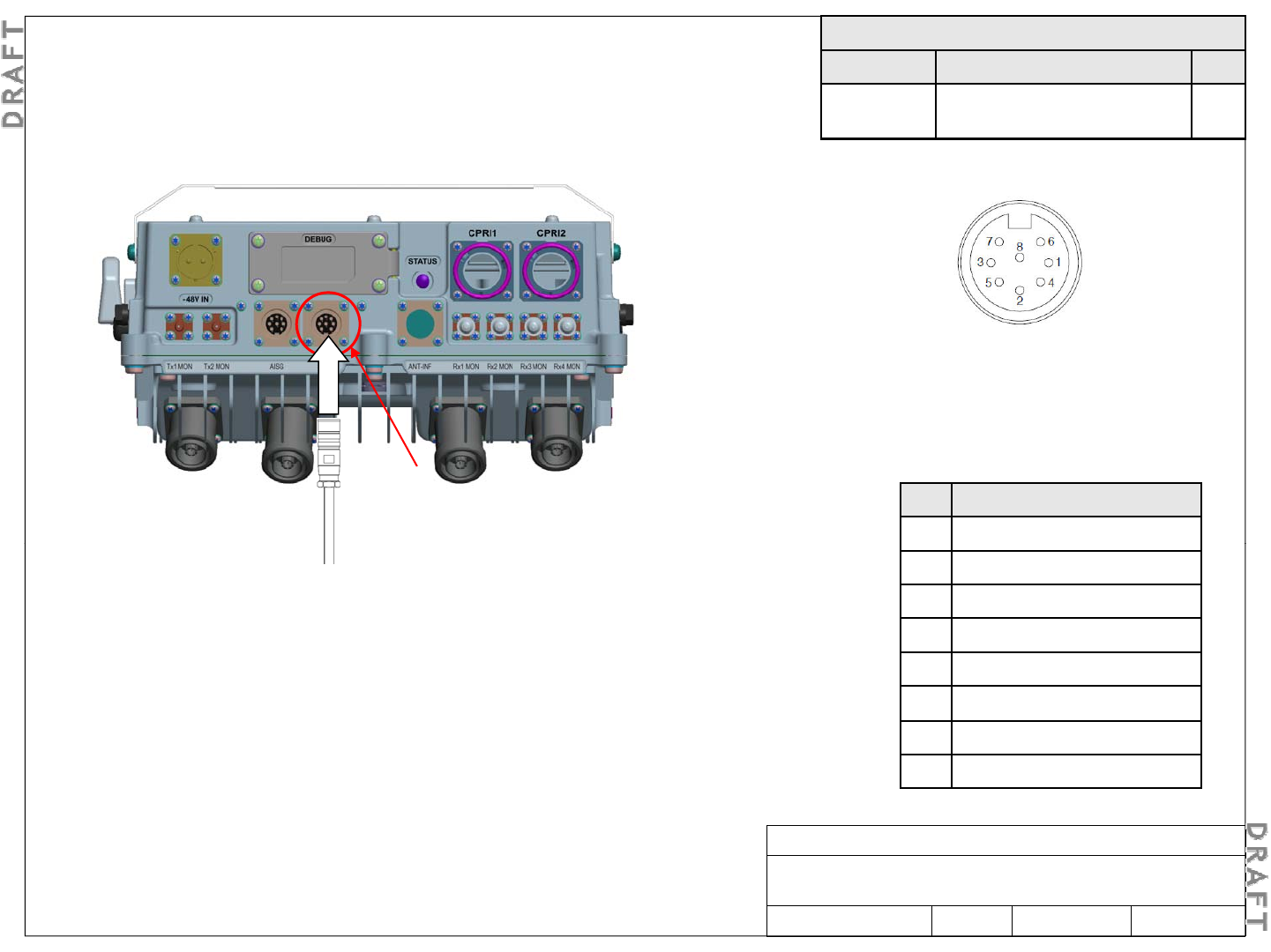
5-6. Route and connect user alarm cables (optional)
Install and route the alarm cables from the alarm ports to the alarm
distribution frame.
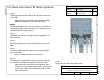
Connector pin configuration
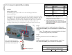
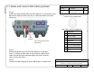
Step 5
Plug the alarm cable connectors into the alarm ports
and hand tighten the outer connector shell to secure
h bl
Step 2
Pin Designation
1 User_ALM_4_P
Alarm cable terminal configuration
alarm
(output)
t
h
e
ca
bl
es.
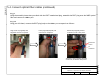
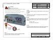
Step 2
Connect the alarm cables to the distribution frame.
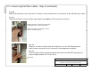
Step 3
Using an ohmmeter or multi-meter, verify the continuity between the alarm
cable connector pins and the distribution frame (DF)
2 User_ALM_3_RTN
3 User_ALM_1_P
4 User_ALM_2_RTN
5 User_ALM_2_P
cable connector pins and the distribution frame (DF)
.
Note: This measurement is performed on the alarm cable connector
(RRH side) with a loop back of each pair (one by one) on the alarm DF
side. Using a multi-meter, check that no short circuit appears between
each pair and the shielding wires.
6 User_ALM_4_RTN
7 User_ALM_3_P
8 User_ALM_1_RTN
Alcatel-Lucent RRH 2x60-B4
Alcatel-Lucent – Internal
Proprietary – Use pursuant to Company instruction
3MN-01520-0002-RJZZA Issue 0.02 March 2014
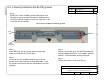
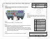
Step 4
Remove the protective cover from the alarm ports on the RRH.
Sheet 19 of 24