
Datasheet


Page 3
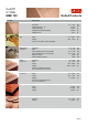
180° Bending
0
1
2
3
4
5
6
R200/R220 R240 R290 R360
Tem per
relative Bending Radius R/T
bending edge transvers to rolling direction
bending edge in rolling direction
90° Bending
0
1
2
3
4
5
6
R200/R220 R240 R290 R360
Temper
relative Bending Radius R/T
bending edge transvers to rolling direction
bending edge in rolling direction
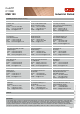
Bending Properties Thickness: ≤
0.5 mm
Bending Properties*
Temper Thickness
Range
Bending
90°
Bending
180°
Trans-
vers
Parallel Trans-
vers
Parallel
mm R/T R/T R/T R/T
R220 ≤
0.5 0 0 0 0
R240 ≤
0.5 0 0 0 0
R290 ≤
0.5 0 0.5 0.5 1
R360 ≤
0.5 1 2 1.5 2.5
* Measured at sample width 10 mm according to EN 1654
Possible bending radius = (R/T)
x thickness
Cu-ETP
C11000
KME 100
Industrial
Rolled
Bending test according to EN ISO 7438 is
done with 10 mm wide samples. Smaller
samples in general –
as well as lower
thickness –
allow a lower bending radius
without cracks. If needed we supply bending
optimized temper classes that far exceed
standard quality.
Please take care when comparing with ASTM
E 290 results, there the bend definition
direction is contradictory.
Bending Definition
Transverse = good way
Parallel = bad way
R
ol
l
i
n
g
di
r
ect
i
o
n
180° Parallel
90° Parallel
90° Transverse
180° Transverse
Minimum Bending Radius Calculation
To find out the minimum possible bending
radius take the R/T value from the list.
Example: R/T = 0.5 and thickness 0.3 mm
Minimum radius = (R/T) x thickness
= 0.5 x 0.3 mm = 0.15 mm
Bending test with R240 in 5 mm thickness
showed crack free bending at R/T ≥
0.35 for
90°
and 180°
bending in parallel and
transverse direction.
Bending of 5 mm thickness