
User Manual
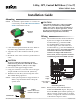

VEB-43/VEP-45 Series 2-Way (1/2 to 3") NPT Control Ball Valves 2 Installation Guide© 2013 KMC Controls, Inc. 050-019-53G
KMC Controls, Inc.
19476 Industrial Drive
New Paris, IN 46553
574.831.5250
www.kmccontrols.com
info@kmccontrols.com
For additional instructions on wiring, feedback selec-
tor, and actuator/signal range reset (auto-mapping),
see the MEP-4000/4800 Series Installation Guide or
(fail-safe) MEP-4200/4500/4900 Series Installation
Guide.
Maintenance
No routine maintenance is required. Each compo-
nent is designed for dependable, long-term reliabil-
ity, and performance. Careful installation will also
ensure long-term reliability and performance.
Operation
After the mechanical and electrical installations
have been completed, cycle the actuator to verify
the direction of rotation for normal operation and
fail-safe if so equipped.
More Information
For non-fail-safe wiring,
auxiliary switches, feed-
back/direction selectors,
actuator/signal range reset
(auto-mapping), and other
information, see the MEP-
4000/4800 Series Installa-
tion Guide.
Formodels,specications,
and additional information,
see the VEB-43/VFB-43
Series Data Sheet on the
KMC web site.
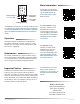
CL Wiring (MEP-4x52)
–
–
–
~/+
+
Control Signal
2–10 VDC
Power Supply
24 VAC/VDC
OUT (Green)
2–10 IN (White)
T
COM (Black)
~24 V (Red)
+
Feedback Output
1–5 or 2–10 VDC
For information on assem-
bling a quick-mount “V”
actuator on a valve body, see
the HPO-5074 Installation
Guide.
For fail-safe wiring,
auxiliary switches, feed-
back/direction selectors,
actuator/signal range
reset (auto-mapping), and
other information, see the
MEP-4200/4500/4900 Series
Installation Guide.
Important Notices
The material in this document is for information
purposes only. The contents and the product it
describes are subject to change without notice. KMC
makes no representations or warranties with respect
to this document. In no event shall KMC be liable for
any damages, direct or incidental, arising out of or
related to the use of this document.