
Install Instructions
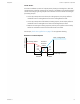
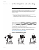
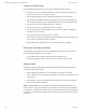
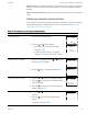
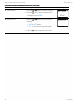
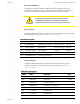
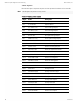
Table Of Contents
- Contents
- Section 1: About the controllers
- Section 2: Installing the controllers
- Section 3: Changing the room setpoint
- Section 4: Configuring the controllers
- Section 5: Balancing airflow
- Section 6: Application drawings
- Section 7: Sequences of operation
- Section 8: System integration and networking
- Appendix A: K‑factors
- Index

Bulbs are open If one or both bulbs are open—as tested with an ohm meter—it indicates the
voltage or current on the network exceeded safe levels. Correct the conditions and replace
the bulbs.
Bulbs not inserted correctly One lead from one or both of the bulbs are not inserted into the
socket.
Setting up network communications
Set the network communication settings before placing a controller on the network. Setting
network settings requires entering Password 2 which is described in the topic Getting
started with configuration on page 21.
Procedure Detailed steps Sensor display
1 Starting display
1. Start at the temperature display.
2.
Press the and buttons together.
l If Password 2 is not required, the display
changes to CNFG.
l If required, enter Password 2. The display
changes to CNFG when Password 2 is correct.
72
12S1
PSW2
OOOO
2 Select the CNFG display
1.
From the CNFG display, press the or buttons to
advance to the COMM display.
2.
Press the
Set
Point
button. The display changes to DID.
CNFG
COMM
3 Enter the device instance.
1.
Press the or buttons to change the first digit.
2.
Press the
Set
Point
button to select the next digit. Repeat
for all seven digits.
3.
When the
Set
Point
button is pressed for the last digit, the
display changes to MAC.
D ID
OO72O69
4 Enter the MAC address.
1.
Press the or buttons to change the MAC
address.
2.
Press the
Set
Point
button to save the selected MAC
address.
The display changes to BAUD.
MAC
11
Table 8–1 Procedure to set up network communications
SimplyVAV Section 8: System integration and networking
Revision H 65