
Install Instructions
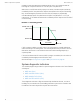
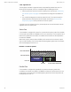
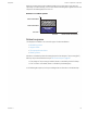

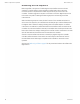
Table Of Contents
- Contents
- Section 1: About the controllers
- Section 2: Installing the controllers
- Section 3: Changing the room setpoint
- Section 4: Configuring the controllers
- Section 5: Balancing airflow
- Section 6: Application drawings
- Section 7: Sequences of operation
- Section 8: System integration and networking
- Appendix A: K‑factors
- Index

Time proportioned reheat
For controllers configured for time proportional reheat, the duty cycle of a binary triac output
varies over a 10 second period. For example, if the Reheat loop is at 50%, the reheat output is
ON for 5 seconds and OFF for 5 seconds. If the Reheat loop is less than 10%, the reheat
output remains at zero.
See the topic Time proportional reheat on page 45 for an application drawing.
Illustration 7–5 Time proportional reheat operation
Room temp increase
HTG SP-2F
HTG SPAN
loop %
0
100
10
HTG %
Reheat
Floating reheat
If the controller is configured for floating reheat, it controls two binary triac outputs to drive
the inputs of a tri-state actuator connected to a valve. If the Reheat loop is less than 30%, the
valve is driven closed. If the loop is greater than 70%, the valve is driven open. If the loop is in
between 30% and 70%, no valve action is taken.
See the topic Floating reheat on page 46 for an application drawing.
Illustration 7–6 Floating reheat operation
HTG %
DRIVE
OPEN
DRIVE
CLOSED
loop %
0
100
70
Reheat
30
HTG SP
HTG SPAN
-2F
Room temp increase
NO ACTION
SimplyVAV Section 7: Sequences of operation
Revision H 59