
Install Instructions
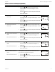
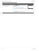
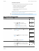
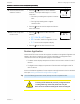
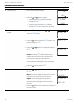
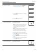
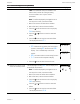
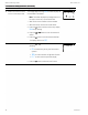
Table Of Contents
- Contents
- Section 1: About the controllers
- Section 2: Installing the controllers
- Section 3: Changing the room setpoint
- Section 4: Configuring the controllers
- Section 5: Balancing airflow
- Section 6: Application drawings
- Section 7: Sequences of operation
- Section 8: System integration and networking
- Appendix A: K‑factors
- Index

Procedure Steps Sensor display
2 Select the CNFG display.
1.
From the CNFG display, press the or buttons to
advance to COMM and the BLNC display.
2.
Press the
Set
Point
button to select BLNC. The display
advances to PRI.
3.
Press the
Set
Point
button to select PRI.
CNFG
COMM
BLNC
PRI
3 Measure and enter the actual
maximum primary airflow
The display begins flashing PMAX and also displays the
actual airflow at the bottom.
Note: The airflow will attempt to stabilize on the
highest value for either the cooling or heating
maximum airflow even if only one mode is
operational.
Note: The airflow displayed by the digital sensor in
this stepf is the actual, uncorrected airflow.
1. Wait for the maximum airflow value to stabilize.
2. With a flow hood, measure the actual airflow.
3.
Press the
Set
Point
button to advance to the entry display.
PMAX stops flashing.
4.
Press the or buttons to enter the measured
airflow.
5.
Press the
Set
Point
button to save the measured airflow.
The display changes to PMIN.
PMAX
OO
4 Measure and enter the actual
minimum primary airflow
The display begins flashing PMIN and also displays the
actual airflow at the bottom.
PMIN
OO
The airflow balancing procedure (continued)
Section 5: Balancing airflow KMC Controls, Inc.
38 Revision H