
Install Instructions
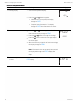
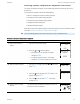
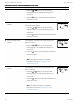
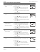
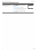
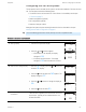
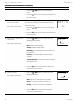
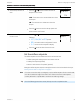
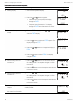
Table Of Contents
- Contents
- Section 1: About the controllers
- Section 2: Installing the controllers
- Section 3: Changing the room setpoint
- Section 4: Configuring the controllers
- Section 5: Balancing airflow
- Section 6: Application drawings
- Section 7: Sequences of operation
- Section 8: System integration and networking
- Appendix A: K‑factors
- Index

Procedure Detailed steps Sensor display
1 Starting display
1. Start at the temperature display.
2.
Press the and buttons together.
l If Password 2 is not required, the display
changes to CNFG.
l If required, enter Password 2. The display
changes to CNFG when Password 2 is correct.
72
12S1
PSW2
OOOO
2 Select the flow setpoint
display.
1.
From the CNFG display, press the or buttons to
show the CNFG display.
2.
Press the
Set
Point
button to select the CNFG options. The
display changes to STPT.
3.
Press the or buttons to change the display to
FLOW.
4.
Press the
Set
Point
button to select FLOW. The display
changes to MNCL.
CNFG
STPT
FLOW
3 Set the cooling minimum
airflow limit.
1.
Press the or buttons to set the minimum limit
for cooling airflow. The setpoint changes in 1 CFM
increments.
2.
Press the
Set
Point
button to save the setpoint and advance
to the next function.
OO
MNCL
4 Set the cooling maximum
airflow limit.
1.
Press the or buttons to set the maximum limit
for cooling airflow. The setpoint changes in 1 CFM
increments.
2.
Press the
Set
Point
button to save the setpoint and advance
to the next function.
3SO
MXCL
5 Set the axillary airflow
setpoint.
Not used for all models.
This setpoint sets the airflow for when reheat is active
auxiliary airflow.
200
AUXF
Procedure to set the airflow setpoints
Section 4: Configuring the controllers KMC Controls, Inc.
30 Revision H