
Install Instructions
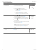
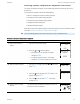
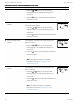
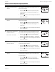
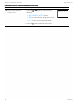
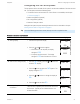
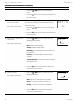
Table Of Contents
- Contents
- Section 1: About the controllers
- Section 2: Installing the controllers
- Section 3: Changing the room setpoint
- Section 4: Configuring the controllers
- Section 5: Balancing airflow
- Section 6: Application drawings
- Section 7: Sequences of operation
- Section 8: System integration and networking
- Appendix A: K‑factors
- Index

Procedure Detailed steps Sensor display
1.
Press the or buttons to set the primary K-
factor.
2.
Press the
Set
Point
button to save the entry and advance to
the next function.
4 Set the secondary VAV
terminal unit K-factor.
Not used in all models.
The K-factor is supplied by the manufacturer of the VAV
terminal unit. Typically it is on the label with the unit
airflow information.
1.
Press the or buttons to set the secondary K-
factor.
2.
Press the
Set
Point
button to save the entry and advance to
the next function.
9O4
SKFT
5 Set the mode of reheat for the
terminal unit.
Not used in all models.
1.
Press the or buttons to choose one of the
following reheat options.
None—Reheat is not enabled.
Staged—Enables staged reheat.
Modulating—The analog reheat output varies from
0-10 volts DC.
Floating—The reheat outputs control a tristate
actuator.
Time proportional—A 24-volt triac output controls a
thermal wax valve.
2.
Press the
Set
Point
button to save the reheat option and
advance to the next function.
NONE
REHT
6 Set the fan option.
Not used in all models.
1.
Press the or buttons to choose one of the
following fan options.
None—No fan is connected to the controller.
Series—The VAV unit includes a series fan.
Parallel—The VAV unit includes a parallel fan.
2.
Press the
Set
Point
button to save the fan option and
advance to the next function.
NONE
FAN
Procedure to set the box functions (continued)
Section 4: Configuring the controllers KMC Controls, Inc.
28 Revision H