SimplyVAV Application and Installation Guide Revision H
KMC Controls, Inc. ©2018, KMC Controls, Inc. NetSensor, WinControl, and the KMC logo are registered trademarks of KMC Controls, Inc. AppStat, BACstage, FlexStat, FullBAC, KMC Connect, KMC Connect Lite, KMC Converge, KMC Converge GFX, KMC Conquest, TotalControl, SimplyVAV, and the SimplyVAV logo are trademarks of KMC Controls, Inc. All rights reserved.
SimplyVAV Contents Co n ten ts Contents 3 Section 1: About the controllers Specifications Accessories and replacement parts Available models Safety considerations 5 6 9 10 10 Section 2: Installing the controllers Setting the rotation limits Mounting on a VAV terminal box Connecting an airflow sensor Connecting inputs and outputs Connecting room temperature sensors Connecting a DAT sensor Connecting power Maintenance 13 13 14 15 15 15 16 17 18 Section 3: Changing the room setpoint 19 Section 4: Co
Contents KMC Controls, Inc.
SimplyVAV Se c t i o n 1: About the controllers This section provides a description of the SimplyVAV series of controllers. It also introduces safety information. Review this material before selecting, installing, or operating the controllers. The SimplyVAV series of controllers are an easy and unique approach to operating a wide variety of VAV terminal units.
Section 1: About the controllers KMC Controls, Inc. BAC-8007 Model BAC-8007 is supplied with inputs, outputs, and sequences of operation for the following functions.
SimplyVAV Section 1: About the controllers Binary outputs Binary outputs are configured to represent BACnet binary output objects. No field configuration is required. For details on application specific output connections see the section Application drawings on page 41.
Section 1: About the controllers KMC Controls, Inc. Regulatory l UL 916 Energy Management Equipment l BACnet Testing Laboratory listed as an application specific controller (ASC). l CE compliant l FCC Class B, Part 15, Subpart B and complies with Canadian ICES-003 Class B This device complies with part 15 of the FCC Rules.
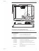
SimplyVAV Section 1: About the controllers Dimensions 6.53 in. 166 mm 4.89 in. 124 mm ON CTS 1 2 4.25 in. 108 mm 0.77 in. 19 mm 6.00 in. 152 mm 2.14 in. 54 mm 1.92 in. 49 mm Accessories and replacement parts The following accessories and replacement parts are available from KMC Controls, Inc.
Section 1: About the controllers KMC Controls, Inc. Sensor cables HSO-9001 Cable: Ethernet, 50 foot HSO-9011 Cable: Ethernet, 50 foot, Plenum Rated Surge suppressors KMD-5567 EIA-485 surge suppressor for MS/TP networks Replacement parts HPO-0054 Replacement bulbs HPO-0063 Replacement two-pin jumper Dual duct actuator TSP-8001 VAV actuator with airflow inputs (required for dual duct) Airflow sensors For VAV terminal units without airflow pickup tubes, order one of the following sensors.
SimplyVAV Section 1: About the controllers Danger Danger represents the most severe hazard alert. Bodily harm or death will occur if danger guidelines are not followed. Warning represents hazards that could result in severe injury or death. Warning Caution Note: Tip: Revision H Caution indicates potential personal injury or equipment or property damage if instructions are not followed. Notes provide additional information that is important.
Section 1: About the controllers 12 KMC Controls, Inc.
SimplyVAV Se c t i o n 2: In s t al l i n g t h e c o n t r o l l e r s This section provides important instructions and guidelines for installing the SimplyVAV controllers. Carefully review this information before installing the controller. Installing SimplyVAV includes the following topics that are covered in this section.
Section 2: Installing the controllers KMC Controls, Inc. To set the rotational limits, do the following 1 Turn the controller over so you have access to the back. 2 Manually rotate the actuator fully clockwise as viewed from the back. 3 Remove the stop screw from its storage location and clean any debris from the threads. 4 Insert the screw into the correct stop position hole. 5 Tighten the screw only until the head touches the plastic in the bottom of the recess.
SimplyVAV Section 2: Installing the controllers Connecting an airflow sensor An airflow sensor is incorporated as one of the inputs to the controller. Remove the plugs and connect the tubing from the pitot assembly to the airflow sensor inputs next to the drive hub.
Section 2: Installing the controllers KMC Controls, Inc. Connect the controller to sensors with standard Ethernet cables up to 75 feet long. See the installation guide supplied with the sensors for sensor installation instructions. Illustration 2–4 Connecting to a sensor Ethernet cable Maximum 75 feet Connecting a DAT sensor The Discharge Air Temperature sensor is required for automatic changeover and for VAV terminal units with reheat.
SimplyVAV Section 2: Installing the controllers Connect a 10 kΩ, Type 3 thermistor temperature probe to the discharge air temperature input. The input includes the internal pull-up resistor. An STE-1401 sensor is suitable for this application. Follow the instructions supplied with the sensor for installation. l l For DAT limiting and reheat, install the sensor in the airflow after the reheat unit. See the topic, Advanced options on page 33 to enable discharge air temperature control.
Section 2: Installing the controllers KMC Controls, Inc. Maintenance SimplyVAV controllers require no routine maintenance. If necessary, clean with a damp cloth and mild soap.
SimplyVAV Se c t i o n 3: C h an g i n g t h e r o o m s e t p o i n t This section covers topics for the end user in a facility. Changing the SimplyVAV user functions with an STE-8001 or STE-8201 are limited to changing the active setpoints in a room. The setpoints are entered or changed using the buttons and display on the front of the sensor. Quick start to changing setpoints 1. Press any button to begin changing setpoints. 2. If required, enter Password 1. 3. Press the up or down setpoint value.
Section 3: Changing the room setpoint KMC Controls, Inc. Changing room setpoints (continued) Procedure Steps Sensor display 3 Set the active cooling setpoint. 1. Press the or buttons to change the cooling setpoint temperature. The setpoint changes in increments of 0.5 degrees. 2. Press the Set Point button to save the value. 745 COOLING The display advances to set the heating setpoint. 4 Set the active heating setpoint. 1. Press the or buttons to change the heating setpoint temperature.
SimplyVAV Se c t i o n 4: Configuring the controllers This topics in this section are advanced topics for control technicians and engineers. The configuration functions that are accessible through an STE-8000 series digital sensor are all of the values and settings that are entered during the installation and commissioning of a VAV terminal unit. Typically, these functions do not change after the installation and commissioning process.
Section 4: Configuring the controllers KMC Controls, Inc. Enter the configuration mode Procedure 1 Starting display Detailed steps Sensor display 1. Start at the temperature display. 72 12S1 2. Press the and buttons together. l If Password 2 is not required, the display changes to CNFG. l 2 Enter Password 2. If required, enter Password 2. The display changes to CNFG when Password 2 is correct. 1. Press the and buttons together and hold them down until the display changes to PSW2. 2.
SimplyVAV Section 4: Configuring the controllers Entering system temperature setpoints and limits The system temperature setpoints set the operational parameters and limits for the VAV terminal unit. The temperature setpoints include the following items.
Section 4: Configuring the controllers KMC Controls, Inc. Procedure to set the temperature setpoints (continued) Procedure Detailed steps Sensor display 1. Press the or buttons to set the minimum cooling setpoint. The setpoint will change in 0.5° increments. 2. Press the button to save the setpoint and advance to the next function. Set Point 4 Set the maximum heating setpoint. This setpoint limits the highest temperature a user can enter as the active setpoint. 1.
SimplyVAV Section 4: Configuring the controllers Procedure to set the temperature setpoints (continued) Procedure 7 Set the unoccupied cooling setpoint. Detailed steps Sensor display This setpoint is used as the active setpoint when the space is unoccupied. UNCL 1. Press the or buttons to set the unoccupied cooling setpoint. The setpoint will change in 0.5° increments. 8OO 2. Press the button to save the setpoint and advance to the next function. Set Point 8 Set the unoccupied heating setpoint.
Section 4: Configuring the controllers KMC Controls, Inc. Procedure to set the temperature setpoints (continued) Procedure 12 Select a new configuration function or exit. Detailed steps 1. Press the following: or buttons to select one of the l BOX, FLOW, ADVC, or RSTR options l BACK to choose another configuration function. l EXIT to return to the temperature display. 2. Press the 26 Sensor display Set Point STPT button to select the next function.
SimplyVAV Section 4: Configuring the controllers Configuring the VAV Box options The box options set the controller for the specific mechanical installation of the VAV terminal unit. The box options include the following items. l The K-factor for the VAV terminal unit. If the K-factor is not available, see the topic K-factors on page 71.
Section 4: Configuring the controllers KMC Controls, Inc. Procedure to set the box functions (continued) Procedure Detailed steps 1. Press the factor. Sensor display or buttons to set the primary K- 2. Press the button to save the entry and advance to the next function. Set Point 4 Set the secondary VAV terminal unit K-factor. Not used in all models. The K-factor is supplied by the manufacturer of the VAV terminal unit. Typically it is on the label with the unit airflow information. 1.
SimplyVAV Section 4: Configuring the controllers Procedure to set the box functions (continued) Procedure Detailed steps 7 Set the damper direction to Sensor display 1. Press the or buttons to which direction to damper moves to close. close. DDIR CCW CCW—The actuator turns counterclockwise to close the damper. CW—The actuator turns clockwise to close the damper. 2. Press the button to save the damper option and advance to the next function. Set Point 8 Select a new configuration 1.
Section 4: Configuring the controllers KMC Controls, Inc. Procedure to set the airflow setpoints Procedure 1 Starting display Detailed steps Sensor display 72 1. Start at the temperature display. 12S1 2. Press the and buttons together. l If Password 2 is not required, the display changes to CNFG. l 2 Select the flow setpoint display. If required, enter Password 2. The display changes to CNFG when Password 2 is correct. 1. From the CNFG display, press the show the CNFG display.
SimplyVAV Section 4: Configuring the controllers Procedure to set the airflow setpoints (continued) Procedure Detailed steps Sensor display 1. Press the or buttons to set a value for the auxillary airflow. The setpoint changes in 1 CFM increments. 2. Press the button to save the setpoint and advance to the next function. Set Point 6 Set the heating minimum airflow limit 1. Press the or buttons to set the minimum limit for heating airflow. The setpoint will change in 1 CFM increments. 2.
Section 4: Configuring the controllers KMC Controls, Inc. Procedure to set the airflow setpoints (continued) Procedure 11 Select a new configuration function or exit. Detailed steps 1. Press the following: Sensor display or buttons to select one of the l STPT, BOX, ADVC, or RSTR options l BACK to choose another configuration function FLOW EXIT. 2. Press the 32 Set Point button to select the next function.
SimplyVAV Section 4: Configuring the controllers Advanced options The advanced options set up passwords and special features in the controller. l Establish or change Password 1 and Password 2 l Set timers for standby and override (optional) l Enable automatic occupancy (optional) l Enable discharge air temperature control (optional) l Calibrate the sensor Setting the advance options requires entering Password 2 which is described in the topic Getting started with configuration on page 21.
Section 4: Configuring the controllers KMC Controls, Inc. Procedure to set the advanced options (continued) Procedure Steps Sensor display 3. When the button is pressed for the last digit, the new password is saved and the display advances. Set Point 4 Change Password 2. Note: Entering four zeros (0000) removes the password. 1. Press the or buttons to change the first digit. 2. Press the button to select the next digit. Repeat for all four digits. Set Point PSW2 OOOO 3.
SimplyVAV Section 4: Configuring the controllers Procedure to set the advanced options (continued) Procedure Steps 9 Set the temperature sensor Sensor display 1. Press the or buttons to set the calibration constant. The setpoint will change in 0.1 minute increments. l For a low input reading enter a positive correction value. calibration constant. l OO CALIB For a high input reading enter a negative correction value. 2. Press the button to save the setpoint and advance to the next function.
Section 4: Configuring the controllers KMC Controls, Inc. Procedure to restore application Procedure 1 Starting display Detailed steps Sensor display 72 1. Start at the temperature display. 12S1 2. Press the and buttons together. l If Password 2 is not required, the display changes to CNFG. l 2 Select the restore settings display. If required, enter Password 2. The display changes to CNFG when Password 2 is correct. 1. From the CNFG display, press the show the CNFG display. or buttons to 2.
SimplyVAV Se c t i o n 5: B al an c i n g ai r f l o w Topics in this section are for control technicians or engineers who will be balancing the airflow in the controllers. The airflow balancing procedure described in this section requires the following items. l l l l A flow hood or other accurate method to measure airflow. An STE-8001 or STE-8201 wall sensor. If the system does not include one of these sensors, temporarily disconnect the installed sensor and connect an STE-8001 as a service tool.
Section 5: Balancing airflow KMC Controls, Inc. The airflow balancing procedure (continued) Procedure 2 Select the CNFG display. Steps Sensor display 1. From the CNFG display, press the or buttons to advance to COMM and the BLNC display. CNFG COMM 2. Press the button to select BLNC. The display advances to PRI. Set Point 3. Press the 3 Measure and enter the actual maximum primary airflow Set Point button to select PRI.
SimplyVAV Section 5: Balancing airflow The airflow balancing procedure (continued) Procedure Steps Sensor display Note: The airflow will attempt to stabilize on the lowest value for either the cooling or heating minimum airflow even if only one mode is operational. Note: The airflow displayed by the digital sensor in this step is the actual, uncorrected airflow. 1. Wait for the minimum airflow value to stabilize. 2. With a flow hood, measure the actual airflow. 3.
Section 5: Balancing airflow KMC Controls, Inc. The airflow balancing procedure (continued) Procedure 7 Measure and enter the actual minimum secondary airflow Steps Sensor display The display begins flashing SMIN and also displays the actual airflow at the bottom. Note: The airflow displayed by the digital sensor in this step is the actual, uncorrected airflow. SMIN OO 1. Wait for the minimum airflow value to stabilize. 2. With a flow hood, measure the actual airflow. 3.
SimplyVAV Se c t i o n 6: A p p l i c at i o n d r awi n g s This section covers the drawings, materials, and instructions for specific VAV applications. Each SimplyVAV model is designed for a specific set of applications. The following topics are for control technicians and engineers that will plan for and install controllers for SimplyVAV applications. Submittal sheets for all of these applications are available from the BAC-8000 series page at KMCControls.com.
Section 6: Application drawings KMC Controls, Inc. Cooling or heating without reheat The BAC-8001 is configured for single-duct cooling VAV control without reheat. Connect the controller as shown in the illustration Cooling or heating application drawing on page 42. A BAC-8005 or BAC-8205 may also be used for this application. For cooling and heating, a duct temperature sensor is required for Discharge Air Temperature limiting and automatic changeover.
SimplyVAV Section 6: Application drawings Staged reheat The staged reheat application is for BAC-8005 or BAC-8205 controllers. The controllers are configured to switch reheat units that are controlled with 24 volts AC. Reheat units with up to three stages of reheat can be controlled by these controllers. l For one-stage, electric reheat or hot water reheat with an on/off valve, use only output terminal BO6. l For two-stage reheat use output terminals BO6 and BO7.
Section 6: Application drawings KMC Controls, Inc. Modulating reheat The modulating reheat application is for a BAC-8005 or BAC-8205 controller. The modulating option for reheat can control either an electric reheat unit with an analog input or a modulating hot water valve. The analog reheat output at output terminal AO3 varies between 0 and 10 volts DC. For cooling and heating, a duct temperature sensor is required for Discharge Air Temperature limiting and automatic changeover.
SimplyVAV Section 6: Application drawings Time proportional reheat The time proportional reheat application is for BAC-8005 or BAC-8205 controllers. This application is typically used in hydronic systems with a hot water reheat coil and a wax top control valve. The reheat output is a triac that can switch up to 1 ampere at 24 volts AC. For cooling and heating, a duct temperature sensor is required for Discharge Air Temperature limiting and automatic changeover.
Section 6: Application drawings KMC Controls, Inc. Floating reheat The floating reheat application is for BAC-8005 or BAC-8205 controllers. Use this application in hydronic systems that are controlled by an actuator with tri-state inputs. The reheat outputs are triacs that can switch up to 1 ampere at 24 volts AC. For cooling and heating, a duct temperature sensor is required for Discharge Air Temperature limiting and automatic changeover.
SimplyVAV Section 6: Application drawings Dual-duct application The dual-duct application is for a BAC-8007 controller. Dual-duct VAV requires a TSP-8001 actuator to be used with the BC-8007 as shown in the illustration Dual-duct wiring diagram on page 47. Submittal sheets for several variations of this application are available from the BAC-8000 series page at KMCControls.com.
Section 6: Application drawings 48 KMC Controls, Inc.
SimplyVAV Se c t i o n 7: Se q u e n c e s o f o p e r at i o n Topics in this section cover the sequences of operation for the SimplyVAV controllers. These are advanced topics for control technicians and engineers. These sequences of operation are descriptions of each major component of the SimplyVAV programming. They are provided as an aid to understanding on how the controllers operate. This section covers the following sequences of operation.
Section 7: Sequences of operation KMC Controls, Inc. STE-6000 series discreet temperature sensors—There are three models of the STE-6000 series sensors compatible with the SimplyVAV controllers. If one of the three sensors is detected, the sensor's temperature is mapped to the Space Temperature Reference value object as the temperature input value. See the topic BACnet objects on page 67 for additional information on value objects.
SimplyVAV Section 7: Sequences of operation Controllers with a connected motion sensor change to Occupied upon the detection of primary airflow and motion in the space. The unit will remain in the OCCUPIED state as long as periodic motion is detected and primary airflow continues. If motion stops, the controller changes to STANDBY. Unoccupied The controller Occupancy mode changes to UNOCCUPIED when it detects a loss of primary airflow.
Section 7: Sequences of operation KMC Controls, Inc. Active setpoint—The active setpoint is the current setpoint. The active setpoint is determined by the following. l l l l l If the space is occupied, the controller uses the occupied setpoint as the active setpoint. If an STE-6014 and STE-6017 is connected, the Active setpoint is set by the dial to be a few degrees above or below the Occupied setpoint. The range of adjustment is set by the variable STBY OFFSET.
SimplyVAV Section 7: Sequences of operation The SimplyVAV controllers use up to three PID loops. l The heating PID loop. l The cooling PID loop. l The discharge air temperature (DAT) loop. For SimplyVAV controllers, the output of either the cooling and heating PID loop is used to calculate the position of the damper. If present, the DAT input and DAT loop controls the Reheat loop.
Section 7: Sequences of operation KMC Controls, Inc. enabled, the VAV terminal will be controlled by the DAT loop. The unit will also limit the Discharge Air Temperature to within 15° F of the Space Temp Reference. When there is a call for heat and the primary air is cool air, the reheat outputs are directly controlled by the DAT Loop and the DAT Setpoint reset based on the output of the Heating loop.
SimplyVAV Section 7: Sequences of operation NEED AHU (BV1) The Need AHU Start value object is set to TRUE (1) for any of the following conditions. l The system mode is UNOCCUPIED and the Cooling loop or the Heating loop is greater than 100% for longer than 10 minutes. l The system mode is OCCUPIED or STANDBY. l Either of the Motion Override or Local Override variable objects are TRUE (1).
Section 7: Sequences of operation KMC Controls, Inc. Fan operation The SimplyVAV controllers support both series and parallel fan powered VAV units. For either type of fan operation, the fan is controlled through the following terminals. l l A binary output triac controls a 24-volt fan starting circuit. See the topic Configuring the VAV Box options on page 27 for the procedure to configure the controller for a fan. A 0-10 volt DC analog output controls the speed of the fan.
SimplyVAV Section 7: Sequences of operation When the unit Occupancy state is UNOCCUPIED, the fan starts and runs at minimum speed only on a call for heating. The fan starts when the Heating loop is greater than 5% and stops when the Heating loop is less than 1%. Illustration 7–3 Parallel fan operation MAX FAN SPEED OCCUPIED MIN FAN SPEED UNOCCUPIED/ STANDBY FAN OFF HTG SP ROOM TEMP INCREASE Reheat sequence The SimplyVAV controllers can control four types of reheat installations.
Section 7: Sequences of operation KMC Controls, Inc. Modulating reheat If the controller is configured for modulating reheat, it controls an analog reheat unit with 010 volts DC at the analog reheat output. On a call for reheat, the reheat output is modulated over the span of the Reheat loop. If the Reheat loop is less than 10%, the reheat output remains at zero. The reheat is set to zero if the Cooling loop is active. See the topic Modulating reheat on page 44 for an application drawing.
SimplyVAV Section 7: Sequences of operation Time proportioned reheat For controllers configured for time proportional reheat, the duty cycle of a binary triac output varies over a 10 second period. For example, if the Reheat loop is at 50%, the reheat output is ON for 5 seconds and OFF for 5 seconds. If the Reheat loop is less than 10%, the reheat output remains at zero. See the topic Time proportional reheat on page 45 for an application drawing.
Section 7: Sequences of operation KMC Controls, Inc. Balancing airflow sequence Balancing airflow is the process of calibrating the internal airflow sensor to a known standard. In the field, airflow is measured with an airflow hood or other measuring instrument and then compared to the airflow measurements from the sensor in the controller.
SimplyVAV Section 7: Sequences of operation Dual duct A dual duct installation consists of separate primary heating and cooling ducts, both with control dampers and airflow monitoring. For this type of installation a SimplyVAV BAC-8007 controls the cooling air (primary) damper and a TSP-8001 actuator controls the heating air (secondary) damper. l l l As the space temperature rises above the cooling setpoint, the primary airflow is modulated from the Cooling Minimum flow to the Cooling Maximum Flow.
Section 7: Sequences of operation 62 KMC Controls, Inc.
SimplyVAV Se c t i o n 8: Sy s t e m i n t e g r at i o n an d n e t wo r ki n g Topics in this section cover integrating the controllers into a building automation network. These are advanced reference topics for control technicians and engineers. The controllers can be installed as standalone controllers or they can be connected to a BACnet MS/TP network.
Section 8: System integration and networking KMC Controls, Inc. Connections and wiring Use the following principles when connecting a controller to an MS/TP network: l l l Connect no more than 128 addressable BACnet devices to one MS/TP network. The devices can be any mix of controllers or routers. For best network performance, limit the MS/TP network size to 32 controllers. Use twisted pair, shielded cable with capacitance of no more than 51 picofarads per foot for all network wiring.
SimplyVAV Section 8: System integration and networking Bulbs are open If one or both bulbs are open—as tested with an ohm meter—it indicates the voltage or current on the network exceeded safe levels. Correct the conditions and replace the bulbs. Bulbs not inserted correctly One lead from one or both of the bulbs are not inserted into the socket. Setting up network communications Set the network communication settings before placing a controller on the network.
Section 8: System integration and networking KMC Controls, Inc. Procedure to set up network communications (continued) Procedure 5 Enter the baud Detailed steps 1. Press the 2. Press the Sensor display or Set Point buttons to select a new baud. button is save the selected baud. The display returns to COMM. 6 Advance or exit 1. Press the following: buttons to select one of the l BLNC or CNFG options l EXIT to return to the temperature display. 2.
SimplyVAV Section 8: System integration and networking BACnet objects The SimplyVAV controllers are BACnet Application Specific Controller (ASC) that are composed of standard BACnet objects. This section lists the objects that are likely to be monitored by a standard BACnet operator workstation to verify system operation. Caution Changing the configuration of any object may result in unpredictable operation of a controller and damage to equipment that is under control of a SimplyVAV controller.
Section 8: System integration and networking KMC Controls, Inc. Value objects BACnet value objects represent setpoints or other operational conditions in the controller. Note: Not all objects are present in every model.
SimplyVAV Section 8: System integration and networking Analog value objects (continued) Object Name Description AV36 DAT STPT Discharge Air Temp Setpoint AV37 SAT CHANGEOVER SAT Changeover Temperature AV38 LOCAL OVRD TIME Local Override Timer AV39 STANDBY TIME Standby Timer (motion) AV40 STANDBY TRIGGER Standby Trigger AV43 MEASURED MAX Measured Maximum AV44 MEASURED MIN Measured Minimum AV45 PRI SAVE MIN FLO Primary Saved Minimum Airflow AV47 DAT MAXIMUM Maximum DAT Setpoint
Section 8: System integration and networking KMC Controls, Inc.
SimplyVAV A p p e n d i x A : K - f ac t o r s To set up a VAV controller, a K-factor must be entered into the controller. Typically, this is part of the airflow chart that the manufacturer places on the VAV unit. If this information is missing and not available from the manufacturer, use the K-factor in the following chart.
Appendix A: K-factors 72 KMC Controls, Inc.
SimplyVAV Index bulbs network 63 replacement 9 A C accessories 9 actuator mounting 14 rotation limits 13 shaft size 6 specifications 6 speed 6 airflow balancing 37 maximum limit 29 minimum limit 29 sensor 15 setting limits 29 applications 41 cooling only without reheat 42 cooling/heating without reheat 42 dual duct 47 floating reheat 46 modulating reheat 44 staged reheat 43 three-stage reheat 43 time proportional reheat 45 automatic occupancy enabling 33 sequence 50 auxillary flow sequence 53 setting 2
KMC Controls, Inc.
SimplyVAV setting changeover 23 limits 23 occupied 23 room 19 standby 23 shaft size for actuator 6 specifications 6 standby sequence 50 setting timer 33 submittal sheets 41 system diagnostic indicators 54 T three-stage reheat 43 time proportional reheat 45 timers, setting 33 transformer wiring 17 tri-state reheat 46 two-stage reheat 43 U units to display 35 unoccupied sequence 50 temperature setpoints 23 V value objects 68 W wiring application drawings 41 connecting power 17 DAT sensor 16 MS/TP network