
User Manual
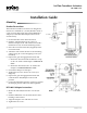

TSP-5000 Series 3 Installation Guide
Setup
The TSP-50xx is factory calibrated to function with
anSSS-1000seriesdierentialpressureowsensor.
Using 24" of 1/4" OD x 0.040" wall “FR” instrument
and control tubing, a 3/8" to 1/4" barb union adapter,
and 1" of 3/8" OD x 0.062 “FR” tubing for both con-
nections:
1. Connect “H” port to the “H” (High) side of the
SSS-100x sensor.
2. Connect the “L” port to the “L” (Low) side of the
SSS-100x sensor.
NOTE: Tomaintainaclosecorrelationwiththe
factory calibration (for 0 to 3300 fpm),
installations must use exactly 24 inches of
the 1/4" tubing without restrictions such as
ingsorkinks.
NOTE: TheSSS-1000seriessensormustbe
mounted with the arrow pointing in the
directionoftheairow.
Calibration
TheTSP-50xxhasarangeof0–3,300fpmwitha1–5
VDCvelocityoutputsignalwhenusinganySSS-1000
seriesvelocitypickup.Finetuningtoaspecicrange
is possible.
NOTE: Thewiringaccessdoormustberemoved
to complete any of these adjustments. See
removal instructions in the Connections
and Wiring section.
Tosetarange:
1. Apply the desired velocity pressure maximum
owtothe“H”and“L”ports.
2. AdjusttheSPANpotentiometeruntilthe1–5
VDCVelocityOutputsignalindicates5VDC
(readbetweenterminals“out”and“–”).
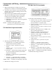
Motor Operation Test
TSP-5003/5023 Tri-State Models
1. Temporarily disconnect wires at “C MTR” and the
“CW” and “CCW” terminals next to it (NOT the
“CW” and “CCW” terminals next to “W POT”).
2. Jumperthe“CMTR”terminaltothe“–”terminal.
3. Jumperthe“CW”terminaltothe“24VAC”
terminal. The shaft drive hub should be rotating
in the CW direction.
4. Jumperthe“CMTR”terminaltothe“–”terminal.
5. Jumperthe“CCW”terminaltothe“24VAC”
terminal. The shaft drive hub should be rotating
CCW.
6. If the actuator does not perform in this manner,
check the wiring.
TSP-5002/5022 Proportional Models
1. Temporarily disconnect the thermostat connection
at Terminal “IN”.
2. Jumper“IN”terminaltothe“16VDC”terminal.
The green Open LED should illuminate. The shaft
drive hub should be rotating the damper open
(until fully open). If the damper is rotating closed,
change the “CW” or “CCW” to Close jumpers.
3. Jumper“IN”terminaltothe“–”terminal.Thered
Close LED should illuminate. The shaft drive hub
should be rotating the damper closed (until fully
closed). If the damper is rotating open, change the
“CW” or “CCW” to Close jumpers.