
User Manual

TSP-5000 Series 2 Installation Guide
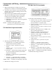
Connections and Wiring
All Models
1. Remove the TSP-50xx’s wiring access door by
pulling back on the door’s tab and lifting upward.
2. Access for wire or cable is via two 5/8" (16 mm)
diametersnap-inshuerbushingslocatedonthe
boomofthecover.
3. Removethesnap-inshuerbushingandreplace
with one the following connectors as needed.
(Connectorsnotsupplied,orderseparately):
a. HMO-4518for1/2"exibleconduit.
b. HMO-4520 compression connector for plenum
rated cable.
c. HMO-4526 for rigid 1/2" conduit.
NOTE: Continuetotheappropriate2–10VDC
proportional or tri-state model section.
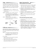
TSP-5002/5022 Proportional Models
4. Wirethetri-stateTSP-50x3asfollows:
a. Terminal “CW” (just left of “W POT”) for one side
of the 10K potentiometer (1/3 wa) for optional
position feedback to a controller input.
b. Terminal “W POT” (Wiper Potentiometer) for the
wiper of the 10K pot.
c. Terminal “CCW” (just right of “W POT”) for the
other side of 10K pot.
d. Terminal “CW” (just left of “C MTR”) to 24
VACclockwisemotordrive.
e. Terminal “C MTR” (Common Motor) to
common for CW or CCW motor drive.
f. Terminal “CCW” (right of “C MTR”) to 24
VACCCWmotordrive.
g. Terminal “OUT” (+ output) optional air velocity
readout signal.
h. Terminal “16 VDC” (optional 22 mA power
supply).
i. Terminal “–” optional air velocity readout
reference (and 16 VDC reference if required).*
j. Terminal“–”totheneutralorgroundsideof
the transformer.*
k. Terminal“~”tothephasesideofa24VAC
–15/+20%,50/60Hz,Class2onlytransformer.
*NOTE: Both“–”terminalsareinternallyconnected.
5. Reinstall the wiring access door.
TSP-5003/5023 Tri-State Models
4. WiretheproportionalTSP-50x2asfollows:
a. Terminal“IN”to2–10VDCproportional
signal from thermostat/controller.
b. Terminal “16 VDC” (optional 22 mA power
supply).
c. Terminal “OUT” (+ output) optional air velocity
readout signal.
d. Terminal“–”thermostat/controllersignaland
airvelocityreadoutreference(and16VDC
reference if required).*
e. Terminal“–”totheneutralorgroundsideof
the transformer.*
f. Terminal“~”tothephasesideofa24VAC
–15/+20%,50/60Hz,Class2onlytransformer.
*NOTE: Both“–”terminalsareinternallyconnected.
5. Reinstall the wiring access door.