
User Manual

TSP-5000 Series 1 Installation Guide
Installation Guide
Air Flow Transducer-Actuators
TSP-5000 Series
Mounting
Standard Instructions
The TSP-50xx transducer-actuators are designed to
mount on a standard 1/2" (13 mm) diameter shaft or
a 3/8" (9.5 mm) shaft using the optional HFO-0011
adaptor (see the HFO-0011 Adaptor Instructions
section below).
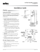
1. Set the TSP-50xx in the desired location.
2. Slide the TSP-50xx directly on to the 1/2"
diameter damper shaft. The shaft must extend a
minimum of 1-3/4" from the mounting surface.
3. Place the non-rotation bracket (supplied) on the
non-rotation tab.
4. Aachtheanti-rotationbrackettothemounting
surface using #8 or #10 self-tapping screws (not
included).
5. Depressthegeardisengagementbuonand:
a. Rotate the drive hub until the indicator stops
at the “90” mark if the damper is clockwise to
close.
b. Rotate the drive hub to the “0” mark if the
damper is counterclockwise to close.
6. Position the damper to full open.
7. Tighten the two 5/16"-18 hex set screws (see
diagram).
8. Depressthegeardisengagementbuonand
rotate the drive hub/damper to the closed
position.
9. Loosen the adjustable end stop, position it against
the damper position indicator, and retighten it.
HFO-0011 Adaptor Instructions
1. Mount the TSP-5003/23 actuator over the 3/8"
shaft.
2. Slide the HFO-0011 over the shaft into the drive
bushing of the actuator.
3. Align the adaptor slots with the set screws.
4. Tighten the set screws.
Mounting 1
Standard Instructions 1
HFO-0011 Adaptor Instructions 1
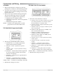
Connections and Wiring 2
All Models 2
TSP-5002/5022 Proportional Models 2
TSP-5003/5023 Tri-State Models 2
Setup 3
Calibration 3
Motor Operation Test 3
TSP-5003/5023 Tri-State Models 3
TSP-5002/5022 Proportional Models 3
Accessories 4
Maintenance 4
More Information 4
Important Notices 4