
Application Guide
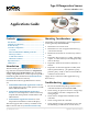
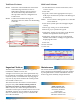
Table Of Contents

Type III Temperature Sensors 1 Applications Guide, AN1013A Rev. B
Applications Guide
Type III Temperature Sensors
STE-1400 and Other Series
Contents
Introduction ...................................................................1
Mounting Considerations ...............................................1
Troubleshooting .............................................................1
Controller Configuration ................................................2
Overview ....................................................................2
BAC-A1616BC BACnet Building Controller ................2
BACstage Software .....................................................2
TotalControl Software ................................................3
WinControl Software..................................................3
Important Notices ..........................................................3
Maintenance ..................................................................3
Troubleshooting
• Be sure the 10,000 ohm pull-up resistors on the
controller board are selected/turned ON.
• Check wiring. To prevent excessive voltage drop,
use a conductor size that is adequate for the
wiring length!
• Check sensor conguration and tables in the
controller.
• Check voltage from the controller.
• Check that the sensor is mounted correctly. (See
the Mounting Considerations section above.)
Mounting Considerations
Depending on the application, space temperature
sensors generally should NOT be:
• Mounted on an exterior wall.
• Mounted on or near a large thermal mass (e.g.,
concrete block wall).
• Blocked from normal air circulation by obstruc-
tions.
• Exposed to heat sources (e.g., lights, computers,
copiers, or coee makers) or to sunlight (at any
time of the day).
• Exposed to drafts from windows, diusers, or
returns.
• Exposed to air ow through the conduit (from
leaks in plenum ducts)—put plumber’s puy,
painter’s puy, caulk, or other sealant inside the
conduit to block air ow.
Apply what is relevant to other applications (e.g.,
duct sensor).
Introduction
This document gives conguration, troubleshoot-
ing, and other related information for temperature
sensors using Type III thermistors. For mounting,
wiring, and specications, see the respective product
installation guide and data sheet (STE-1400 Series
Data Sheet for STE-14xx sensors).
For information about Type II thermistor sensors,
see:
• STE-6010/6011/6013/6015 Application Guide for
room temperature sensors with optional override
buon and LED indicator.
• STE-6014/6017/6018/6019/6020 Application
Guide for room temperature sensors with rotary
setpoint dials and optional override buon and
LED indicator.
• STE-6012/6016 Application Guide for room
temperature transmiers with LCD displays.
The latest support les are always available on the
KMC Controls web site (www.kmccontrols.com).