
User Guide

SSE-1000/2000 Series 1 Installation Guide
Installation Guide
VAV System Duct Flow Sensors
SSE-1000/2000 Series
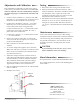
Mounting
The SSE-1000 and SSE-2000 sensors are designed to
mount to the VAV box’s inlet collar. The sensor head’s
foam backing prevents conditioned air leakage.
1. Cut a 7/8" hole in the duct.
2. Insert the sensor.
3. Align the sensor horizontally to maintain
calibration at zero airow.
4. Fasten with two 3/16" sheet metal screws.
5. Add a 2" x 4" stando type conduit box if wiring
must be run through conduit.
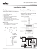
Connections and Wiring
See the diagrams below. See also the CEP-4000 illustra-
tion on the next page.
• Sensorterminals 1, 2, and 3 connect to CEP-4000
terminals 1, 2, and 3 respectively.
• SSE-2000 series terminals “X” and “Y” connect to
a heat/cool relay module.
CAUTION
To prevent damage to the SSE series sensors, do not
touch or handle the interior wire windings.
Sample Application
(Cooling/Heating Changeover)
Mounting 1
Connections and Wiring 1
Adjustments and Calibration 2
Testing 2
Maintenance 2
More Information 2