
Instruction Manual


SAE-1111/1112/1162 Carbon Monoxide (CO) Detectors 1 Installation Guide
Installation Guide
Carbon Monoxide (CO) Detectors
SAE-1111/1112/1162
Mounting 1
SAE-1111/1112 Space Mount 1
SAE-1162 Duct Mount 1
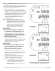
Wiring 2
Operation 3
Warm-Up Mode 3
Normal Mode 3
Alarm Mode 3
Configuration 4
Test Mode 4
Fault Mode 4
ReCal (Recalibration) Mode 4
Calibration 8
Models 9
Accessories 9
Maintenance 9
Important Notices 9
More Information 9
SAE-1111/1112 Space Mount
Install the unit at least ve feet above the nished
oor of the area to be controlled. Do not install
near doors, windows, supply air diusers of other
known air disturbances. Avoid areas prone to vibra-
tion or rapid temperature change.
1. On the mounting surface, mark and drill the four
mounting holes (for screws) and remove any
debris from all holes.
2. Aach the unit to the surface by threading four
screws through the four mounting holes.
3. Remove the two cover screws (if installed),
release the latch, and swing open the cover.
4. Insert wiring through a knockout.
5. After wiring, conguring, and testing the
unit (see later sections), close the cover and
(optionally) secure it with two (supplied) self-
tapping screws.
SAE-1162 Duct Mount
Choose a mounting location in a straight section of
a return air duct. Mount at least 5 feet (or 7.5 duct
diameters) from corners and other items that may
cause disturbances in the air ow. Avoid areas prone
to vibration or rapid temperature change.
1. Cut a 1-1/8 or 1-1/4 inch hole in the duct for the
air sampling probe.
2. Insert the probe through the hole, align the unit
so that the duct air ow is parallel with the side
vent holes in the probe (air ows directly into
the probe holes), and mark the four enclosure
mounting holes.
3. Drill the four mounting holes (for screws) and
remove any debris from all holes.
4 . Insert the sampling probe into the duct.
5. Aach the unit to the ductwork by threading four
screws through the four holes on the outside of
the enclosure.
6. Remove the two cover screws (if installed),
release the latch, and swing open the cover.
7. Insert wiring through a knockout. After wiring a
duct sensor, ll the knockout hole with plumber’s
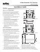
Mounting
145 mm
5.7"
101 mm
4"
114 mm
4.5"
89 mm
3.5"
ALARM
64 mm
2.5"
240 mm
9.5"
26 mm
1"
177 mm
7.0"
145 mm
5.7"
101 mm
4"
114 mm
4.5"
89 mm
3.5"
ALARM
64 mm
2.5"
SAE-1111/1112
SAE-1162
puy, caulk, or other sealant to prevent air
inltration from the conduit.
8. After wiring, conguring, and testing the
unit (see later sections), close the cover and
(optionally) secure it with two tapping screws.