
User guide
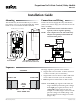

REE-5525 Relay Module 2 Installation Guide
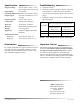
Troubleshooting
• Check the wiring.
• Check the voltage from the controller, measured
from Terminal – (under 24 VAC) to Terminal
0–10 IN. (See the Sequence chart on the previous
page.)
• Check the voltage across the triac and load. (See
the chart below.)
© 2014 KMC Controls, Inc. 809-019-05A
KMC Controls, Inc.
19476 Industrial Drive
New Paris, IN 46553
574.831.5250
www.kmccontrols.com
info@kmccontrols.com
Important Notices
The material in this document is for information pur-
poses only. The contents and the product it describes
are subject to change without notice. KMC Controls,
Inc. makes no representations or warranties with
respect to this document. In no event shall KMC Con-
trols, Inc. be liable for any damages, direct or incidental,
arising out of or related to the use of this document.
Specifications
NOTE: Triac outputs are for 24 VAC loads only.
Maintenance
No routine maintenance is required, however protec-
tion from extremes of humidity and dirt is recom-
mended. Careful installation will also ensure long
term reliability and performance.
Supply Voltage 24 VAC (+20%/–15%) @ 1 VA
plus output loads, Class 2 only
Input Signal 0 to 10 VDC
Switching Dierential 2 VDC (see Sequence chart)
Output Types Optically isolated triacs, zero
crossing
Output Capacity 30 VAC max., 12 VA
Connections Plated screw terminals
Wire Size 14–22 AWG, stranded
Material Beige ame-retardant plastic
Weight 2 oz. (57 grams)
Approvals SASO PCP Registration KSA
R-103263
Temperature Limits
Operating 32 to 120° F (0 to 49° C)
Shipping –40 to 160° F (–40 to 71° C)
Stage Status
Normal Triac Voltage (Approximate and With Load)
Across Load
(Actuator Common to
Terminal 1 or 2)
Across Triac
(Terminal SC to
Terminal 1 or 2)
On 24 VAC 1 VAC
BOTH Off 0 VAC 24 VAC