
User guide

© 2010 KMC Controls, Inc. 809-019-04D
KMCControls,Inc.
19476 Industrial Drive
New Paris, IN 46553
574.831.5250
www.kmccontrols.com; info@kmccontrols.com
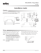
Maintenance
No routine maintenance is required, however protec-
tion from extremes of humidity and dirt is recom-
mended. Careful installation will also ensure long
term reliability and performance.
NOTE: For more information about the CEP-4000/
CTE-1004 example, see the CEP-4000
Series VAV Flow Controllers-Actuators
Application Guide.
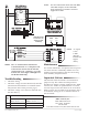
NOT
E: The“C”terminaldoesNOTdenote
Common/Neutral.“C”isthephaseside
ofthe24VAC(andisalsothesidethe
contactorshavein“common”).“9”isthe
neutralside.Triacstages1through3are
for24VACloadsonly.
NOTE: “T” input
is 0 to
6 VDC.
(See the
Thermostat
Signal
chart.)
Stage
Status
Normal Triac Voltage (Approximate, and With Load)
Across Load (Terminal C/
Phase to Terminal 1, 2, or 3)
Across Triac (Terminal 9/
Neutral to Terminal 1, 2, or 3)
On 24 VAC 1 VAC
Off 0 VAC 24 VAC
Troubleshooting
• Check the wiring.
• Check the voltage from the thermostat/controller
(measured from Terminal T to Terminal 9/Neu-
tral). (See the chart on the previous page.)
• Check the voltage across the triac and load. (See
the chart below.)
Important Notices
The material in this document is for information
purposes only. The contents and the product it
describes are subject to change without notice. KMC
Controls, Inc. makes no representations or warran-
ties with respect to this document. In no event shall
KMC Controls, Inc. be liable for any damages, direct
or incidental, arising out of or related to the use of
this document.
Stages
24 VAC
GND
(–)
OUT
(+)
(Alternate Direct
Control from an
Analog or DDC
Controller)