
Manual


REE-1005 1 Installation Guide
Installation Guide
Heat/Cool Changeover Relay Module
REE-1005
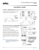
Mounting
The REE-1005 can be mounted directly to a control
box surface or in a 2 x 4" electrical handy box. To
conceal the module, add a blank cover.
Connections and Wiring
Wire as shown in the examples for single duct heat-
ing/cooling changeover using one box to supply hot
or cold air to the space.
The factory setpoint is 77° F (25° C).
Terminal A is an optional auxiliary ow limit trig-
ger signal (usually connected to Terminal A on a
CTE-1004, CTE-5104, or REE-1012). When the relay
module senses heating mode, terminal A goes high
(around 6.8 VDC with a 9.1 VDC supply or 13.8 VDC
with a 16 VDC supply). This terminal can also be
used to daisy chain more than one REE-1005 together
by wiring Terminal “A” to Terminal “Y” on the next
relay.
Mounting 1
Connections and Wiring 1
Maintenance 2
Important Notices 2
NOTE: See the CEP-4000 Series Applications
Guide and the CSP-5001/5002 Applications
Guide for additional information on
applications.