
User Guide

RCC-1000/1100 Series 1 Installation Guide
Installation Guide
Pneumatic Relays
RCC-1000/1100 Series
Mounting
The RCC-1000 Series models are light-weight and
suitable for in-line mounting without a bracket.
The RCC-1100 Series models include a right-angle
bracket for surface mounting. RCC-1000/1100 relays
are not position sensitive.
Connection and Calibration
All Models
• All port connections use 1/4" OD polyethylene
tubing.
• Use only clean, dry control air. No aempt
should be made to use any other medium.
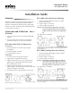
RCC-1001/1101/1012/1112 Reversing
Connection:
1. Connect Main air to Port M, 20 psi (30 psi
maximum).
2. Connect Output to Port B.
3. Connect Input to Port S.
Calibration:
1. Connect an accurate gauge to Port B.
2. Apply main air pressure to Port M.
3. Apply the desired cross-over pressure input
signal (9 psi for RCC-1001/1101 and 8 psi for
RCC-1012/1112) to Port S.
4. Adjust until the desired cross-over pressure
output signal is reached (9 psi for RCC-1001/1101
and 8 psi for RCC-1012/1112).
5. Check the pressures and readjust as necessary.
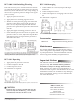
RCC-1006/1106 Low Pressure Selecting
1. Connect Output (the lower of the two input
pressures) to Port B.
2. Connect Input 1 to Port S1.
3. Connect Input 2 to Port S2.
NOTE: Becarefulwhenapplying“one-pipe”
restrictedsignalstoS2sincetherelay’s
outputisderivedfromtheairappliedto
S2.
No calibration is required.
Main air is Port M, output is Port B, input is Port S.
The output, Port B, is the lower of the two input pressures applied to Ports S1 and S2. Take
CARE when applying “one-pipe” restricted signals to S2 since the relay’s output is derived
from the air applied to S2.
Mounting 1
Connection and Calibration 1
All Models 1
RCC-1001/1101/1012/1112 Reversing 1
RCC-1006/1106 Low Pressure Selecting 1
RCC-1008/1108 High Pressure Selecting 1
RCC-1009/1109 Switching/Diverting 2
RCC-1013 Repeating 2
RCC-1102 Averaging 2
Accessories 2
Maintenance 2
Important Notices 2
RCC-1008/1108 High Pressure Selecting
1. Connect Output (the higher of the two input
pressures) to Port B.
2. Connect Input 1 to Port S1.
3. Connect Input 2 to Port S2.
NOTE: ThesignalsappliedtoPortsS1andS2
mustcomefromrelievingtypedevices.
DoNOTsupplyfromNOorNCportsof
divertingrelaysorsolenoidairvalves.
No calibration is required.
No adjustments need to be made. The design allows for positive switching between signals,
and the non-transmitted signal is internally blocked. The signals applied to Ports S1 and S2
must come from “relieving” type devices. Do NOT supply from NO or NC ports of diverting
relays or solenoid air valves.