
Instruction Manual
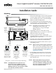

MEP-7200/7500/7800 Series 4 Installation Guide
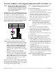
Fail-Safe Direction (MEP-7x5x)
All fail-safe models oer selectable CW/CCW fail
direction and the option to turn o the fail-safe using
a slide switch to the right of the terminals.
Important Notices
The KMC logo is a registered trademark of KMC
Controls, Inc. All rights reserved. No part of this
publication may be reproduced, transmied, tran-
scribed, stored in a retrieval system, or translated
into any language in any form by any means without
the wrien permission of KMC Controls, Inc.
The material in this document is for information
purposes only. The contents and the product it
describes are subject to change without notice.
KMC Controls, Inc. makes no representations or
warranties with respect to this document. In no event
shall KMC Controls, Inc. be liable for any damages,
direct or incidental, arising out of or related to the
use of this document.
Specifications
See the MEP-7500/7800 Series Data Sheet.
© 2013 KMC Controls, Inc. 031-019-01H
KMC Controls, Inc.
19476 Industrial Drive
New Paris, IN 46553
574.831.5250
www.kmccontrols.com
info@kmccontrols.com
Accessories
See the MEP-7xxx Applications Guide.
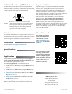
More Information
For models, specica-
tions, and additional
information, see the
MEP-7500/7800 Series
Data Sheet on the KMC
web site.
For accessories, trouble-
shooting, master/slave
wiring, torque selection,
links to sample applica-
tions, and other informa-
tion, see the MEP-7xxx
Applications Guide on
the KMC web site.
Maintenance
No routine maintenance is required. The motors are
permanently lubricated. Careful installation will also
ensure long term reliability and performance.
NOTE: After initial connection or reconnection to
power, proper fail-safe operation might
be delayed up to 40 seconds (until the
capacitors are fully charged).
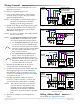
24 VAC/VDC
Power In
Feedback
Potentiometer
(MEP-7xx3 only)
24 VAC/VDC
Power In
24 VAC/VDC
Power In
2–10 VDC Control Signal
4–20 mA Control Signal
1–5 or 2–10 VDC Feedback Signal
Control Signal Common
(MEP-7x52 Only)
24 VAC/VDC
Power In
2
1
Switch/Contact
Jumper
Feedback
Potentiometer
(MEP-7xx3 only)
Feedback
Potentiometer
(MEP-7xx3 only)
CW
CCW
CW
CCW
1
2
Applications
For possible proportional heating/cooling applica-
tions using the CTE-5202 electronic thermostat, see
the CTE-5202 Applications Guide.
For valve applications, see information on:
• VEB-53 Series Two-Way, Flanged Ball Valves (4
to 6")
• VEB-56 Series Three-Way, Flanged Ball Valves
(4 to 6")
• VEF-53 Series Two-Way, Rubber-Lined, Buer-
y Valves (2 to 6")
• VEF-56 Series Three-Way, Rubber-Lined, But-
tery Valves (2 to 6")
The latest support les are always available on the
KMC Controls web site (www.kmccontrols.com).
Illustration 7—Fail-Safe Direction Switch