
Instruction Manual

MEP-7200/7500/7800 Series 2 Installation Guide
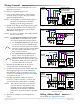
Wiring (Master/Slave)
See the MEP-7xxx Applications Guide.
24 VAC/VDC
Power In
Feedback
Potentiometer
(MEP-7xx3 only)
24 VAC/VDC
Power In
24 VAC/VDC
Power In
2–10 VDC Control Signal
4–20 mA Control Signal
1–5 or 2–10 VDC Feedback Signal
Control Signal Common
(MEP-7x52 Only)
24 VAC/VDC
Power In
2
1
Switch/Contact
Jumper
Feedback
Potentiometer
(MEP-7xx3 only)
Feedback
Potentiometer
(MEP-7xx3 only)
CW
CCW
CW
CCW
1
2
Illustration 2—MEP-7xx2 Wiring (Proportional)
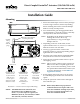
Wiring (General)
1. Loosen the screws on the tethered access cover
and remove the cover.
2. Slide the conduit ing plate out.
3. Using a utility knife or drill, cut the red plug
to accept wiring or replace the plug with an
application-specic ing.
NOTE: The red plugs (or similar ings) protect
the internal components from debris,
helping to ensure long actuator life.
4. Thread wires through the plugged opening and
connect to the terminal block according to the
appropriate model and options desired. (See
Illustrations 2 through 5.)
NOTE: For your convenience, the wiring terminal
block is removable.
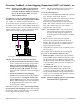
NOTE: For two-position wiring on a fail-safe tri-
state actuator (see Illustration 5), choose
one of these (jumpered) rotation options:
1. For clockwise rotation when the 24 volt
circuit switch/contact is closed, jumper
the 24 VAC terminal to the CW terminal
and select CCW on the Fail switch. When
the circuit opens, the actuator rotates
fully counterclockwise.
2. For counterclockwise rotation when
the 24 volt circuit switch/contact is
closed, jumper the 24 VAC terminal to
the CCW terminal and select CW on the
Fail switch. When the switch opens, the
actuator rotates fully clockwise.
5. Reinstall the terminal block on the pins (if
removed) and the conduit ing plate.
6. For MEP-7xx2 (proportional) models, adjust the
auto-mapping range reset, rotation direction,
and feedback voltage as needed. See Direction,
Feedback, & Auto-Mapping (Proportional MEP-
7xx2 Models) on page 3.
7. For MEP-7x5x models, adjust the fail-safe
(clockwise, counter-clockwise, or o) selector
switch, beside the terminal block, as needed.
NOTE: After initial connection or reconnection
to power (until the capacitors are fully
charged), fail-safe operation might be
delayed up to 20 seconds for the MEP-
725x/755x or up to 40 seconds for the MEP-
785x.
8. Reinstall the tethered cover and tighten the
screws.
Illustration 3—MEP-7x01/7x03 Wiring (Tri-State, Non-Fail-Safe)
Illustration 4—MEP-7x51/7x53 (Normal) Wiring
(Tri-State, Fail-Safe)
Illustration 5—MEP-7x51/7x53 Two-Position Wiring
(Tri-State, Fail-Safe)
24 VAC/VDC
Power In
Feedback
Potentiometer
(MEP-7xx3 only)
24 VAC/VDC
Power In
24 VAC/VDC
Power In
2–10 VDC Control Signal
4–20 mA Control Signal
1–5 or 2–10 VDC Feedback Signal
Control Signal Common
(MEP-7x52 Only)
24 VAC/VDC
Power In
2
1
Switch/Contact
Jumper
Feedback
Potentiometer
(MEP-7xx3 only)
Feedback
Potentiometer
(MEP-7xx3 only)
CW
CCW
CW
CCW
1
2