
Instruction Manual

MEP-7200/7500/7800 Series 1 Installation Guide
Installation Guide
Mounting 1
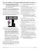
Wiring (General) 2
Wiring (Master/Slave) 2
Direction, Feedback, & Auto-Mapping (Proportional MEP-7xx2 Models) 3
Fail-Safe Direction (MEP-7x5x) 4
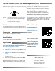
Maintenance 4
Accessories 4
Specifications 4
Applications 4
Important Notices 4
More Information 4
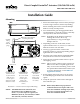
Mounting
Illustration 1—Overview (Direct-Coupled Mounting)
1. Ensure that the damper can move freely through
its entire range of motion, and x any binding
before installing the actuator. Turn the damper
blade to its fully closed position.
2. Press and hold the gear disengagement buon
(see Illustration 1), rotate the actuator to the fully
closed position, and release the buon.
NOTE: Depending on the damper-seal design,
backing the actuator o its stop
approximately 5° may provide tight
damper shut-o.
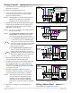
3. Depending on the size of the shaft, use the
optional shaft insert as is, reverse it, or remove it.
Slide the actuator onto the shaft.
4. Leaving a gap between the actuator and
mounting surface to prevent any binding, nger-
tighten the nuts on the V-bolt.
5. Insert the non-rotation bracket (supplied HMO-
4535) into the slot at the base of the actuator.
6. Secure the non-rotation bracket with two (2) #8
self-tapping screws.
NOTE: The two holes at the top of the actuator are
not for use in direct-coupled applications.
They are for remote mounting, such as with
the optional HLO-1020 Crank Arm Kit. (For
accessory information, see the MEP-7xxx
Applications Guide.)
7. Evenly tighten the V-bolt nuts to 110 to 120 in-
lb. while keeping the shaft insert centered and
square.
8. Verify the operation of the actuator through its
full rotational cycle.
5"
8"
2-7/16"
3/8"
3"
10 1/8"
Gear disengagement button
Position insert as
shown for 3/8"
to 9/16" round
shafts or 5/16"
to 3/8" square
shaft (1/2" round
shafts on center)
Position insert as
shown for 5/8"
to 13/16" round
shafts or 1/2"
to 5/8" square
shafts (3/4"
round shafts on
center)
Remove insert
for 7/8" to
1.05" round
shafts (1.05"
round shafts
on center)
INSERT
POSITION INSERT AS SHOWN FOR
3/8" to 9/16" ROUND SHAFTS or
5/16" to 3/8" SQUARE SHAFTS.
(1/2" ROUND SHAFTS ON CENTER)
INSERT
POSITION INSERT AS SHOWN FOR
5/8" to 13/16" ROUND SHAFTS or
1/2" to 5/8" SQUARE SHAFTS.
(3/4" ROUND SHAFTS ON CENTER)
REMOVE INSERT FOR
7/8" to 1.05" ROUND SHAFTS.
(1.05" ROUND SHAFTS ON CENTER)
HMO-4535 non-rotation
bracket (provided)
INSERT
POSITION INSERT AS SHOWN FOR
3/8" to 9/16" ROUND SHAFTS or
5/16" to 3/8" SQUARE SHAFTS.
(1/2" ROUND SHAFTS ON CENTER)
INSERT
POSITION INSERT AS SHOWN FOR
5/8" to 13/16" ROUND SHAFTS or
1/2" to 5/8" SQUARE SHAFTS.
(3/4" ROUND SHAFTS ON CENTER)
REMOVE INSERT FOR
7/8" to 1.05" ROUND SHAFTS.
(1.05" ROUND SHAFTS ON CENTER)
Shaft insert
INSERT
POSITION INSERT AS SHOWN FOR
3/8" to 9/16" ROUND SHAFTS or
5/16" to 3/8" SQUARE SHAFTS.
(1/2" ROUND SHAFTS ON CENTER)
INSERT
POSITION INSERT AS SHOWN FOR
5/8" to 13/16" ROUND SHAFTS or
1/2" to 5/8" SQUARE SHAFTS.
(3/4" ROUND SHAFTS ON CENTER)
REMOVE INSERT FOR
7/8" to 1.05" ROUND SHAFTS.
(1.05" ROUND SHAFTS ON CENTER)
5"
8"
2-7/16"
3/8"
3"
10 1/8"
Conduit
fitting
plate
and red
plugs
Direct-Coupled ControlSet
®
Actuators (120/180/320 in-lb.)
MEP-7200/7500/7800 Series
NOTE: Before 2014, MEP-7xx2 proportional
models had 0–10 VDC inputs and 0–5 or
0–10 VDC feedback. Starting in Jan. 2014,
they have 2–10 VDC inputs and 1–5 or
2–10 VDC feedback instead.
NOTE: The MEP-7200 series (120 in-lb.) was
discontinued. Use an MEP-75xx (180
in-lb.)—or, if less torque is required, an
MEP-48xx (80 in-lb., non-fail-safe) or MEP-
49xx (90 in-lb., fail-safe) instead.
Shaft insert