
User Guide

MEP-4200/4500/4900 Series 4 Installation Guide© 2014 KMC Controls, Inc. 039-019-01G
KMC Controls, Inc.
19476 Industrial Drive
New Paris, IN 46553
574.831.5250
www.kmccontrols.com
info@kmccontrols.com
Maintenance
No routine maintenance is required. Careful
installation will ensure long term reliability and
performance.
Direction, Feedback, and Auto-Mapping (MEP-4xx2)
3. Return selector switch #2 to the required
increasing voltage direction before the reset
nishes. The reset process is complete after the
actuator has moved to the CW limit and has
begun to position normally.
4. Verify that the actuator travels completely across
the new range.
NOTE: For example, after completing the auto-
mapping program, the new actuator stroke
is 0–80°. A 6 VDC input signal (halfway
between 2–10 VDC) will then drive the
actuator to the 40° position (50% of its
adjusted range) and the feedback voltage
will be 3 VDC if switch #1 is set at the 1–5
VDC position or 6 VDC if switch #1 is set at
2–10 VDC.
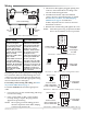
MEP-4xx2 proportional models oer selectable
actuator direction and selectable proportional feed-
back of 1–5 VDC or 2–10 VDC (in either direction).
To access the selector switches, loosen the (2)
screws on the conduit ing and lift up to remove
the ing. The selector switches are shipped from
the factory in the 1–5 VDC (#1 pushed Up) and
CW movement with increasing voltage (#2 pushed
Down) positions (see Illustration 11).
Illustration 11—Feedback/Direction/Mapping Selectors
*NOTE: Selector Switch #2 has two functions:
1. Switch #2 determines the direction to rotate
(CW or CCW) with increasing voltage and
is factory set in the CW position (down). To
change, remove power before ipping the
switch up to the CCW position. Removing
power prevents initiation of the auto-mapping
feature.
2. Switch #2 initiates the auto-mapping
feature. (See description below.) This feature
is initiated only by cycling the switch with
power applied to the unit. The auto-mapping
feature will NOT begin if the switch position is
changed with power removed or in the event
of a power failure.
MEP-4xx2 models also oer a actuator/signal range
reset program (auto-mapping) feature that reassigns
the full 2–10 VDC input signal scale over a reduced
stroke range for more precise control.
NOTE: The auto-mapping feature works best for
ranges that are more than about 45°.
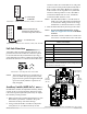
To set the auto-mapping:
1. If desired, use a 7/64-inch hex key wrench to
loosen and position the end-stop screw.
2. After power has been applied to the actuator for
at least 30 seconds (allowing fail-safe capacitors to
charge), ip selector switch #2 (from its required
CW or CCW increasing voltage direction) to start
the reset mode. The actuator will rst move to the
CCW limit. The complete reset process will take
approximately four minutes.
Switch (#1) Feedback (#2)* Direction
Up 1–5 VDC CCW
Down 2–10 VDC CW
More Information
For models, specications,
and additional information,
see the MEP-4200/4500/4900
Series Data Sheet on the
KMC web site.
For accessories, trouble-
shooting, torque selection,
links to sample applica-
tions, and other informa-
tion, see the MEP-4xxx
Applications Guide on the
KMC web site.