
Manual


Document No. 129-361
Installation Instructions
August 3, 2004
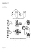
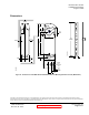
Wiring Diagrams
Modulating Control 24 Vac
MEP-4556xx
M
A
B
S1
S4
S2 S3 S5 S6
1
8
2
9
EA0284R1
Two-position Control 24 Vac
MEP-455100
M
A
B
S1
S4
S2 S3 S5 S6
2
1
EA0281R1
Three-position Control 24 Vac
MEP-455500
M
A
B
S1
S4
S2 S3 S5 S6
1
6
7
GND
PL0004R1
120 Vac Two-position Control
MEP-455300
M
4
NEUTRAL
3
LINE
EA0926R1
Table 2. 24 Vac Wiring.
Standard
Symbol
Function
Terminal
Connection
Color
1 Supply (SP) G Red
2 Neutral (SN) G0 Black
6
Control signal
clockwise
Y1 Violet
7
Control signal
counterclockwise
Y2 Orange
8
0 to 10 Vdc/4 to 20 mA
input signal
Y Gray
9
Output for 0 to 10 Vdc
position indication
U Pink
S1 Switch A Common Q11 Gray/red
S2 Switch A NC Q12 Gray/blue
S3 Switch A NO Q14 Gray/pink
S4 Switch B Common Q21 Black/red
S5 Switch B NC Q22 Black/blue
S6 Switch B NO Q24 Black/pink
Table 3. 120 Vac Two-Position Control.
Standard
Symbol
Function
Terminal
Connection
Color
3 Line L Black
4 Neutral N White
Page 6 of 7
NOTE: These wiring diagrams show options that are no
longer available for certain models. To order models with the
appropriate options, see the MEP-455 series data sheet!
NOTE: Do not order actuator models
based on these diagrams! To order
models with the appropriate options,
see the MEP-455 series data sheet.