
Manual


Document No. 129-361
Installation Instructions
August 3, 2004
EA0288R1
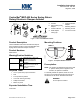
1
2
3
4
OR
EA0289R1
3
4
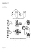
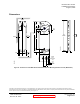
Figure 5. With the Damper Blades in the Desired "0" Position, Place the Actuator on the Shaft.
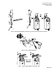
EA0357R2
4 mm
5/32 in.
2 PLACES
6
5
1/2
1/2
g
f
Figure 6. Fasten the Mounting Bracket.
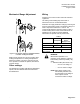
10 mm
13/32 in.
EA0359R2
10 mm
13/32 in.
Apply 7.5 lb-ft
(10 Nm) torque
maximum
77
Figure 7. Fasten the Shaft Adapter to the Damper Shaft.
.
Page 3 of 7