
Manual


Document No. 129-361
Installation Instructions
August 3, 2004
Installation
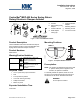
90°
EA0327R1
90°
2
1
2
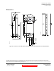
Figure 3. Actuator Mounting Orientation.
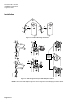
EA0370R2
>20 mm
>3/4 in
<
77 mm
<3 in
3
a
4
5
6
5
4
a
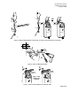
e
b
d
d
90
c
7
6
c
c
c
7
6
SHAFT
ADAPTER
ALIGNMENT
MARK
>
77 mm
>3 in
c
c
b
Figure 4. Shaft Length and Proper Shaft Adapter Location.
NOTE: Place the shaft adapter right next to the alignment mark keeping the mark visible.
Page 2 of 7