
Install Instructions
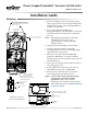
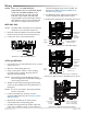
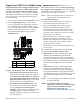
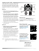
Table Of Contents

MEP-4000/4800 Series 3 Installation Guide
Proportional (MEP-4xx2) Models Setup
Illustration 6—Feedback/Direction/Mapping Selectors
MEP-4xx2 models also oer a actuator/signal range
reset program (auto-mapping) feature that reassigns
the full 0/2–10 VDC input signal scale over a reduced
stroke range for more precise control.
NOTE: The auto-mapping feature works best for
ranges that are more than about 45°.
To set the auto-mapping:
1. If desired, use a 7/64-inch hex key wrench to
loosen and position the end-stop screw.
2. With power applied to the actuator, ip the
Direction switch (from its required CW or
CCW increasing voltage direction) to start the
reset mode. The actuator will rst move to the
CCW limit. The complete reset process will take
approximately four minutes.
3. Return the Direction switch to the required
increasing voltage direction before the reset
nishes. The reset process is complete after the
actuator has moved to the CW limit and has
begun to position normally.
4. Verify that the actuator travels completely across
the new range.
For example, after completing the auto-mapping
program, the new actuator stroke is 0–80°:
• With a 0–10 VDC input, a 5 VDC input signal
(halfway between 0–10 VDC) will drive the
actuator to the 40° position (50% of its adjusted
range) and the feedback voltage will be 2.5 VDC if
the Feedback switch is set at the 0–5 VDC position
or 5 VDC if the Feedback switch is set at 0–10
VDC.
• With a 2–10 VDC input, a 6 VDC input signal
(halfway between 2–10 VDC) will drive the
actuator to the 40° position (50% of its adjusted
range) and the feedback voltage will be 3 VDC if
the Feedback switch is set at the 1–5 VDC position
or 6 VDC if the Feedback switch is set at 2–10
VDC.
NOTE: After automapping, the feedback range will
be equally aected.
NOTE: For more information (including
adjustments, accessories, troubleshooting,
torque selection, and links to sample
applications), see the MEP-4xxx
Applications Guide on the KMC web site.
Proportional actuators are shipped with factory set-
tings of 2–10 VDC input, 1–5 VDC feedback volt-
age, and CW movement with increasing voltage.
To change any seings, access the selector switches
and jumper (see Illustrations 5 and 6) by loosening
the screws on the conduit ing and lifting up to
remove the ing.
1. Select actuator rotation with the Direction switch.
2. Use the Input Range jumper to select either
0–10 or 2–10 for the VDC input range. This also
sets the starting point for the feedback voltage
(e.g., 2–10 VDC input provides a corresponding
feedback voltage of either 2–10 or 1–5 VDC).
Select the desired feedback range with the
Feedback switch.
*NOTE: The Direction switch has two functions:
1. It determines the direction to rotate (CW or
CCW) with increasing voltage and is factory
set in the CW position (down). To change, re-
move power before ipping the switch up to
the CCW position. Removing power prevents
initiation of the auto-mapping feature.
2. It initiates the auto-mapping feature. (See
description below.) This feature is initiated
only by cycling the switch with power
applied to the unit. The auto-mapping feature
will NOT begin if the switch position is
changed with power removed or in the event
of a power failure.
Switch Feedback Direction*
Up 0/1–5 VDC CCW
Down 0/2–10 VDC CW