
Install Instructions
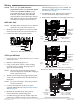
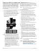
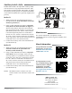
Table Of Contents

MEP-4000/4800 Series 2 Installation Guide
Illustration 3—MEP-4xx1/4x13 TRI-STATE Wiring
Illustration 4—MEP-4xx1/4x13 2-POSITION (3-Wire) Wiring
Illustration 5—MEP-4xx2 Proportional Wiring
Wiring
NOTE: Before Jan. 2014, MEP-40x2/48x2
proportional models had 0–10 VDC inputs
and 0–5 or 0–10 VDC feedback (only).
From 2014 through July 2015, they had
2–10 VDC inputs and 1–5 or 2–10 VDC
(only) feedback instead. Starting in August
2015, all these options were available and
selectable via a jumper and slide switch.
MEP-4003 Only
NOTE: The MEP-4003’s terminals are not enclosed
inside the case as the other models are.
1. Route the cable through the strain relief molded
in the lower left of the case. (See Illustration 2.)
2. Connect the wires to the terminal block.
Illustration 2—MEP-4003 (Only) Wiring
All Except MEP-4003
1. Loosen the screw on the tethered access cover and
remove the cover.
2. Slide the conduit ing plate out.
3. Using a utility knife or drill, cut the red plug
to accept wiring or replace the plug with an
application-specic ing.
NOTE: The red plug (or similar ing) protects
internal components from debris, helping to
ensure long actuator life.
4. Thread wires through the plugged opening and
connect to the terminal block. (See Illustrations 3
through 5.)
NOTE: For your convenience, the wiring terminal
block is removable.
5. Connect and adjust the auxiliary switch if
required (MEP-4x2x only). See Auxiliary Switch
(4x2x) on page 4.
6. Reinstall the terminal block on the pins (if
removed) and the conduit ing plate.
7. For MEP-4xx2 (proportional) models, adjust the
input range, feedback voltage, rotation direction,
and auto-mapping range reset as needed. See
Illustration 5 and Proportional (MEP-4xx2)
Models Setup on page 3.
8. For MEP-4xx1/4x13s, adjust rotation direction
switch if needed (see Illustration 3 and 4).
9. Reinstall the tethered cover and tighten the screw.
CW
COM
CCW
Switch Position:
1 = Rotation is
Direct
0 = Rotation is
Reversed
–
~
Feedback Potentiometer
(MEP-4x13 Only)
Power
Supply
CW
COM
CCW
Feedback Potentiometer
Switch Position:
1 = Rotation is
Direct
0 = Rotation is
Reversed
Contact Position: Open = CW Rotation, Closed = CCW Rotation
(MEP-4x13 Only)
–
~
Power
Supply
Power
Supply
~
–
–
+
Control Signal:
0–10 or
2–10 VDC
–
+
Feedback Output:
1–5 or 2–10 VDC
(with 2–10 VDC Input)
or 0–5 or 0–10 VDC
(with 0–10 VDC Input)
–
~
Power
Supply
Strain Relief