
Application Guide
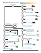
Table Of Contents

KMC Actuators Selection Guide 2 AG150807B
Introduction
This selection guide aids in choosing the best actua-
tor for new or replacement applications. See the data
sheets, installation guides, and application guides
for details of individual products. The application
determines the type of actuator needed.
See Geing Physical with Actuators on the KMC
Controls web site for general information about
actuator types.
Electronic vs. Pneumatic
New installations almost always use electronic
(electric) actuators, but many pneumatic (air) actua-
tors still exist in older installations.
See Pneumatics for the 21st Century on the KMC
Controls web site for general information about
pneumatic actuators. See also Air Today, Digital
Tomorrow: Pneumatic to BAS Conversions for
information about using pneumatic actuators with
building automation systems.
Fail-Safe vs. Non-Fail-Safe
Pneumatic actuators are inherently fail-safe. Fail-safe
electronic actuators incorporate springs or capaci-
tors to provide the power for return when power
is removed. See When Failure Is not an Option:
The Evolution of Fail-Safe Actuators on the KMC
Controls web site for more information about fail-
safe and the advantages of capacitors over springs.
Input Types
Proportional models can accept a 0–10 VDC, 2–10
VDC, and/or a 4-20 mA (dependent on model)
control signal input from a thermostat or controller.
Their position is proportional to the signal. Some
models have a voltage feedback option that provides
a signal proportional to the actual position.
Sample Two-Position Wiring (MEP-4xx4)
–
Power Supply
24 VAC/VDC
T
COM (Black)
~24 V (Red)
~/+
Sample Proportional Wiring (MEP-4xx2)
–
–
–
~/+
+
Control Signal
2–10 VDC
or 0–10 VDC
Power Supply
24 VAC/VDC
OUT (Green)
INPUT (White)
T
COM (Black)
~24 V (Red)
+
Feedback Output
1–5 or 2–10 VDC
or
0–5 or 0–10 VDC
Sample Tri-State Wiring (MEP-4x51)
–
Power Supply
24 VAC/VDC
CW
CCW
T
COM
~24 V
~/+
–
Switch
Position
1 2
Tri-state (or “oating”) models move one direction
while 24 VAC is applied to a set of terminals, and
they move the opposite direction while 24 VAC is
applied to a dierent set of terminals. They hold
their position when no power is applied. (Some
tri-state models can also be wired for two-position
operation if desired.) Some models have a three-wire
potentiometer to provide feedback of the actual
position.
Two-position actuators move one direction when
voltage is applied to a set of terminals, and they re-
turn to the original position when power is removed.