
Manual

FlexStat 12 Operation Guide, Rev. R
NOTE: Not all applications have a modulating
economizer option. Withoutamodulating
economizerselected,DCVwillnotappear
inanymenus,but the (Advanced) CO
2
Sensor menu will remain and the CO
2
ppm
readings will still show on the display.
NOTE: An alarm is generated when the CO
2
level is
too high for too long. See Alarms on page 23.
NOTE: The various Outside Air (OA) % seings
available are the percentage that the OA
damperisopen and not the percentage
of OA ow. These seings should be
measured and set accordingly.
NOTE: SeetheDCVsectionintherelevant
SequenceofOperationoftheFlexStat
ApplicationGuideformoreinformation
aboutthemodesandoptionsdescribedin
generaltermshere.
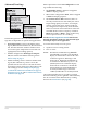
ThethreetypesofDCVcongurationsavailable
are:
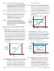
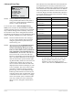
• BASICDCV—Provides simple DCV, modulat-
ing the outside air damper in direct response to
the current CO
2
level with respect to its setpoint.
Basic DCV is much more energy ecient than no
DCV at all, while maintaining adequate IAQ (In-
door Air Quality). It is the easiest DCV method
to congure. However, where VOCs, radon, or
other pollutants become excessive during unoc-
cupied times (with no ventilation), the FlexStat’s
Standard or Advanced DCV conguration is
recommended.
CO
2
Setpoint
0%
Space CO
2
CO
2
Maximum
DCV Signal
Component
to OAD
100%
Basic DCV Configuration
CO
2
Base
Outside Air
Damper
Position
Component
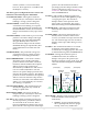
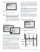
STANDARDDCV—When the BAC-13xxxx seings
are properly congured, this complies with
CATitle24,Section121(c). This would
also apply to a properly congured BAC-
12xxxx with a remote SAE-10xx CO
2
sensor.
Standard DCV, under most conditions, is
somewhat less energy ecient than Basic,
but it enhances IAQ.*
*NOTE: The CO
2
sensors in the BAC-13xxxx series
FlexStats (as well as properly congured
SAE-10xx CO
2
detectors) have been certied
to comply with CA Title 24, Section 121(c),
as well as sub-paragraph 4.F that species
accuracy will be maintained within
tolerance for a minimum of 5 years without
recalibration. Seethedatasheetformore
information.
CO
2
Setpoint
OA Full
OA Area
0%
Space CO
2
CO
2
Maximum
DCV Signal
Component
to OAD
100%
Standard DCV Configuration
CO
2
Base
Outside Air
Damper
Position
Component
“Basic” Signal
“Standard”
Signal
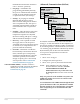
• ADVANCEDDCV—When the seings are
properly congured, this conguration complies
with CATitle24,Section121(c) and ASHRAE
Standard62.1-2007 and follows guidelines by
PortlandEnergyConservation,Inc.(PECI).
Although Advanced DCV is the most complex to
congure, it is more energy ecient than Stan-
dard while still optimizing IAQ.
OA Max
OA Full
OA Area
0%
Space CO
2
CO
2
Maximum
DCV Signal
Component
to OAD*
100%
Advanced DCV Configuration
CO
2
Base
Outside Air
Damper
Position
Component
*Under Normal
Vent Mode operation
(see Vent Mode description)
NOTE: The three graphs above show the DCV
component of the signal to the outside
air damper. Depending on the conditions
and the DCV conguration, the signal
to the damper might be controlled by
Minimum Position, Economizer Loop, or
other components. The maximum of these
component values is used, not the sum