FlexStat™ BACnet Programmable Thermostats Operation Guide Contents Overview................................................................. 3 Applications and Installation.................................... 3 Operation (Basic)..................................................... 4 Navigation........................................................... 4 Room Temp. Setpoint Adjustment........................ 4 H/C, Fan, Occupancy, and Override.................... 4 Main Menu and Settings...................
Resetting the FlexStat............................................. 26 Types of Reset..................................................... 26 Warm and Cold Starts........................................ 26 Restore Factory.................................................. 27 Input, Sensor, and Value Issues........................... 33 CO2 Level Value Is Frozen or Is 0.................... 33 CO2 and DCV Sequences Are Not Working..... 33 CO2 Level Is “Too High”..................................
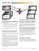
Overview Applications and Installation The award-winning KMC FlexStat series of intelligent temperature/humidity/occupancy-sensing, wallmounted, thermostat/controllers are native BACnet Advanced Application Controllers (B-AAC) for use in a BACnet system. The FlexStat simplifies networked zone control for common packaged HVAC equipment, such as packaged rooftop units, fan coil units, heat pumps, and other similar applications.
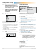
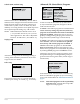
Operation (Basic) Configuration Screens Home Screen WED 9/3 5:43 PM COOL: OCC: FAN: HUM: 31%RH Override Screens SYSTEM MODE SYSTEM ENABLE: AUTO Setp oin t Ad Ov erri just de Up (Setpoint) men t Left Right (Override) (Menu) OCCUPANCY OVERRIDE OCC OVERRIDE: OFF FAN MODES UNOCC: AUTO OCC: AUTO Down (Setpoint) MAIN MENU ABOUT ADVANCED ALARM DATE/TIME SCHEDULE SETPOINTS ion SYSTEM t ADVANCED a r figu APPLICATION n o C CB PROGRAMS COMMUNICATION DATE/TIME DEVICE INPUTS LIMITSAPP
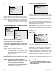
Display Options WED 11/19 3:20 PM WED 11/19 3:22 PM WED 11/19 3:20 PM WED 11/19 3:20 PM COOL: COOL: COOL: COOL: OCC: OCC: OCC: OCC: FAN: FAN: FAN: HUM: 36% RH HUM: 37% RH HUM: 36% RH Fahrenheit decimal values are not displayed by default but can be enabled in the User Interface menu. See Show Temperature Tenths (Decimals) on page 21.
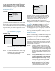
Configuration (Setup) NOTE: Menus shown in this document reflect FIRMWARE VERSION R2.1.0.9 or later. Actual context-sensitive screens are dependent on firmware version, FlexStat model, and options selected. About the FlexStat ABOUT FLEXSTAT MODEL: BAC–141136CE MORE ABOUT FW: FLEXSTAT R1.3.0.
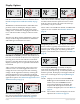
Advanced Menu Auxiliary Heat (Heat Pump Only) Setup AUX HEAT SETUP AUX HEAT: COMP LOCKOUT DELAY (MINS): 60 COMP OAT LOW: 40° F ADVANCED APPLICATION CB PROGRAMS COMMUNICATION DATE/TIME DEVICE INPUTS LIMITS For HPUs, auxiliary heat can be set for none, with compressor lockout, or without compressor lockout. The Advanced Menu displays various submenus. Not all submenus can be seen on the screen at one time. Scroll up or down to see additional submenus.
When BAC-1xxxxx models have an application with the CO2 sensor AND the modulating economizer option enabled, menu items for DCV (Demand Control Ventilation) will appear. For information about the DCV options, see (Advanced) CO2 Sensor (and DCV) on page 11.
reverting from Standby back to Occupied mode (although it may still take some time for the room to reach its normal temperature). See (Advanced) CO2 Sensor (and DCV) on page 11. Sensor Setup SENSOR SETUP IN 2: DISCH AIR TEMP IN 9: CO2 SPACE TEMP: REMOTE -- IN 1 IS ONBOARD -- IN 7 IS REMOTE NOTE: DCV is only available in models with the built-in CO2 sensor. Input 7 (AI7) can be configured for a remote space temperature sensor.
(Advanced) CB (Control Basic) Programs Setback (OAT) Lockout Setup SETBACK LOCKOUT OAT LOCKOUT: ENABLE LOCKOUT TEMP: 30° F Setback OAT lockout is disabled by default. When enabled, AI4 is configured for OAT and the Lockout Temp selection appears in the menu. This may be useful when a system, such as an HPU, may have difficulty recovering from the unoccupied setpoint to the occupied setpoint during very cold weather.
(Advanced) CO2 Sensor (and DCV) During the self-calibration the sensor PPM reading is frozen and will not react to changing CO2. CO2 SENSOR SENSOR INFO CALIBRATION For instructions on calibrating the BAC-14xxxx models with gas, see the CO2 Sensor Calibration section in the FlexStat Application Guide.
NOTE: but it enhances IAQ.* Not all applications have a modulating economizer option. Without a modulating economizer selected, DCV will not appear in any menus, but the (Advanced) CO2 Sensor menu will remain and the CO2 ppm readings will still show on the display. NOTE: An alarm is generated when the CO2 level is too high for too long. See Alarms on page 23. NOTE: The various Outside Air (OA) % settings available are the percentage that the OA damper is open and not the percentage of OA flow.
of them. (If there is a Low Limit alarm, however, these signals are overridden, and the damper is closed.) The three types of configurations have various combinations of the following DCV OPTIONS. CLG DESIGN TEMP = The highest outside air temperature (95° F default) for which the building’s cooling system is designed. CO2 MAX (PPM) = The desired maximum CO2 concentration level during an occupied period (1000 ppm default).
finished and returned the ventilation rate to “normal” operation). • Pre-purge—If enabled in the programming (disabled by default), the space is ventilated with maximum outside air for 60 minutes before the occupied start time. (See Startup.) • Startup—If pre-purge is disabled (default) and the motion sensor detects motion during the 20 minutes after occupied start time, the space is ventilated with maximum outside air until 20 minutes after occupied start time.
For MS/TP EIA-485 communications, the Max Master is the highest MAC address a device will attempt to locate when polling for master devices on the local network. To avoid possible communication issues with the network or a computer connected through a KMD-5576 USB Communicator, the Max Master number should be the lowest number needed for that network. In firmware R2.1.0.7 and later, MS/TP Diagnostics is at the bottom of the MS/TP menu (when MS/TP is the active communications port).
If the FlexStat is used in a BACnet network with UTC (Coordinated Universal Time) synchronization (via broadcasting or addressing a single thermostat) set the UTC Offset value. The UTC Offset value is in minutes and corresponds to the distance of the local time zone to the zero degree meridian. In stand-alone operation or networks that do not have UTC broadcasts, setting this value is not necessary.
may benefit from adjusting the filter weight. Temporarily reducing filter weight may also be helpful for some diagnostic or commissioning purposes (but the defaults should be restored for normal operation). For much more information, see the FlexStat Application Guide. (Advanced) BACnet Device Properties DEVICE INSTANCE: 1 NAME: FlexStat_101 LOCATION: KMC Controls Calibration Offset can be used to calibrate an analog input by changing the value.
(Advanced) PID Loop Configuration (Advanced) Security Levels and Passwords SECURITY ACCESS LEVELS PASSWORDS LOOP CONFIGURATION COOL PROP: 2.0° F HEAT PROP: 2.0° F COOL INTG: 0/hr HEAT INTG: 0/hr ECON PROP COLD: 30° F ECON PROP NORMAL: 15° F ECON INTG: 0/hr ACCESS LEVELS PASSWORDS SETPOINT ADJ: NONE USER: 1000 MAIN MENU: ADMIN OPERATOR: 1234 SYSTEM MODE: OPER ADMIN: 5678 OCC OVERRIDE: USER FAN OCC/UNOCC: OPER This menu allows changes to the default PID (Proportional Integral Derivative) loop values.
(Advanced) Test Menu Items Access Levels Menus Home Screen TEST LCD/KEY TEST User Operator Administrator * = Selectable, Default is User Setpoint Adjust (Up/Down) 4* 4* 4* System Mode (Auto/Heat/Cool/Off) 4* 4* 4* Occupancy Override (On/Off) 4* 4* 4* Fan Modes (Auto/On/Off) 4* 4* 4* 4 4 4 Advanced 4 4 Alarm 4 4 Date/Time 4 4 Schedule 4 4 Setpoints 4 4 4 4 4 4 Main Menu* (Default is User) About System Trend Viewer 4 The test menu merely tests the display’s pixels
Other options that can be user-configured for trend logs include the following: (Advanced) Trend Logs TREND LOGS TREND 1: TRUE TREND 2: TRUE TREND 3: FALSE TREND 4: FALSE TREND 5: FALSE TREND #1 TEMPERATURE LOG TRENDSPACE 6: FALSE REF: AI1 TRENDOBJECT 7: FALSE LOG ENABLE: TRUE INTERVAL (MINS): 10 STOP W/FULL: FALSE TL RESET COUNT: NO APR17 COUNT: 256 APR17 TOTAL CNT: 613 APR17 VIEW LOG BUFFER APR17 APR17 APR17 APR17 #1–SPACE TEMP 1:27PM, 71.4 2:27PM, 71.5 3:27PM, 71.6 4:27PM, 71.8 5:27PM, 76.3 6:27PM, 81.
(Advanced) User Interface (UI) Show Temperature Tenths (Decimals) With R2.0.0.13 and later firmware, Fahrenheit temperature values on the display change in whole degree increments by default, and Celsius values change in 0.5° increments. Changing the default No to Yes will show tenths of a degree values for both scales. See Display Options on page 5.
values persist even after switching between scheduled occupied and unoccupied periods. For example, if a user changes the occupied cooling setpoint to 76°, the occupied cooling setpoint will remain at 76° on subsequent days until a user adjusts it again. The same is true for the unoccupied setpoint. To automatically reset setpoints to default values at particular times, a building automation system can overwrite the setpoint value objects or custom programming can be put into the FlexStat.
• Alarms SAT 4/11 * SERVICE 3:20 PM ALARMS SPACE TEMP ALARM 04/11 COOL: OCC: 04/11/09 08:37:56 FAN: SPACETEMP HUM: 20%RHVALUE = 90.1 PRESENT EXCEEDS HIGH_LIMIT DELETE ALARM? SPACETEMPALARM NO YES NOTE: Time delays and limits can be modified in the corresponding Event Enrollment objects using TotalControl. Additional alarms may be added using TotalControl up to a total of ten. A flashing “SERVICE” on the Home screen indicates an alarm. To view and delete alarms, press: 1.
DCV (Demand Control Ventilation) Schedules DEMAND CONTROL VENT VENT OVERRIDE: OFF VENT MODE: STARTUP SCHEDULE ENTIRE WEEK [MON–SUN] WEEKDAYS [MON–FRI] ENTIRE WEEK WEEKEND [SAT–SUN] 1: 7:30:00 AM ON INDIVIDUAL DAYS 2: 5:15:00 PM OFF HOLIDAYS 3: 4: 5: 6: [—>] DELETES ENTRY This menu appears under the Main Menu only if DCV Advanced Setup is selected. For more options and information, see (Advanced) CO2 Sensor (and DCV) on page 11 and Damper Setup on page 7. To select the desired schedule, press: 1.
will be erased. (Special day schedules will then need to be added again through the INDIVIDUAL DAYS menu). System Modes SYSTEM SYSTEM ENABLE: AUTO OCC OVRIDE (HRS): 1.0 HOLIDAYS HOL1: JAN 1 2009 HOL2: MAR 21 2009 HOL3: MAY 26 2009 HOL4: JULY 4 2009 HOL5: SEPT 1 2009 HOL6: NOV 27 2009 HOL7: NOV 28 2009 This menu allows changes to system enable (auto, off, heat, or cool modes) and occupancy override time.
Trend Viewer 1: 2: 3: 4: 5: 6: 7: Resetting the FlexStat TREND VIEWER SPACE TEMP SPACE HUMIDITY FAN COOL 1 COOL 2 TL APR11 APR11 APR11 APR11 APR11 APR11 APR11 Types of Reset 34 27 19 18 21 If the FlexStat is not operating correctly or if a low limit alarm has occurred, the FlexStat should be reset (reinitialized). Any reset interrupts normal operation, and three types of reset exist: #1 SPACE TEMP 1:27PM, 70.3 2:27PM, 71.3 3:27PM, 71.6 4:27PM, 71.8 5:27PM, 76.3 6:27PM, 81.2 7:27PM, 82.
A cold start does the following in the FlexStat: Restore Factory • (After zeroing out objects during the restart process) returns all object values to their relinquished defaults (until they are updated by the FlexStat’s programs). Restore Factory (restoring the FlexStat to the factory settings) does the following: • Clears present values. • Restarts the controller’s Control Basic programs. • • Leaves configuration and programming intact.
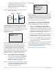
Network Connection MS/TP Network Communication PC Data Port Connection Connect the EIA-485 MS/TP network wiring and set the EOL switches accordingly. (See the Installation Guide for wiring and end-of-line switch information.) From the FlexStat menus, adjust the device instance number, the MAC address, and baud rate from the defaults as necessary. Set the Max Master to the minimum necessary for the network.
Maintenance Accessories Remove dust as necessary from the holes in the top and bottom. Clean the display with a soft, damp cloth and mild soap. See the BAC-12xxxx/13xxxx/14xxxx Series FlexStat Data Sheet. To maintain maximum sensitivity of an optional built-in motion sensor, occasionally wipe dust or dirt off the lens—but do not use any fluid on the sensor. Firmware Upgrade The existing version of firmware can be viewed from the About the FlexStat screen. (See About the FlexStat on page 6).
Troubleshooting Alarm Issues Back-Up Issues Alarm, (False) Fan Fail NOTE: Backing up the existing settings and firmware image before or during the upgrade process (using the Firmware Upgrade Tool, TotalControl, or BACstage) is recommended practice. • Check configuration. Be sure the Fan Status option is not selected when there is no sensor/ switch for it. • Check that the IN2 (fan status) input pull-up resistor switches are fully latched in the correct positions.
• Reduce the Max Master number down to the minimum needed for that network—see (Advanced) Communications (BACnet) on page 14. Cover, Display, and Reset Issues • Install latest driver and check latency settings. See Latency Settings for KMD-5576 Service Bulletin (SB0308A) on the KMC web site. • • See also MS/TP Network Communication Issues below. Cover Binds on Backplate To remove the cover, turn the hex screws in the bottom and top of the FlexStat CLOCKWISE only until they clear the cover.
Display Is Blank (or Erratic) Display Freezes (Buttons Have No Effect) • If the display comes on when a button is pushed, Display Blanking is enabled. (See (Advanced) User Interface (UI) on page 21.) • • Check for a tripped circuit breaker to the transformer. • Carefully remove the FlexStat cover from the backplate. (See Cover Binds on Backplate on page 31.) Check pins and connectors.
Custom Programming and Web Issues Input, Sensor, and Value Issues Control Basic Programs Do Not Work NOTE: NOTE: NOTE: CO2 Level Value Is Frozen or Is 0 The FlexStat has a library of builtin applications and options that are configured through the FlexStat’s display. Beyond these standard configurations, custom changes can be added to a FlexStat using KMC’s BACstage (ver. 2.4.0.26 or later) or TotalControl (ver. 2.0.5 or later).
CO2 Level Is “Too High” • See the CO2 and DCV Sequences Are Not Working section above. • To reduce nuisance complaints by occupants, turn off the visibility of the CO2 level rotation in the display. See (Advanced) User Interface (UI) on page 21. Motion/Occupancy Sensor Does Not Work • The initial firmware (R.1.0.0.0 and earlier) did not support this sensor within the built-in selectable programs. Custom programming was required— see the FlexStat Application Guide.
Also check that its leads are not pinched, shorted, or broken and that the tape holding down the leads is not loose. (Some early models with humidity sensors did not have the additional thermistor—temperature was derived from the same chip that measured humidity.) • • • Using BACstage or TotalControl, check that AI1 (space temp.) is not configured as “Out Of Service.” Check that the FlexStat is NOT mounted on an exterior wall, mounted on or near a large thermal mass (e.g.
Output, Fan, and Relay Issues Analog Output Does Not Work Fan Does Not Run NOTE: CAUTION Do not mistakenly connect 24 VAC to an analog output ground. This is not the same as a relay’s switched common. See the backplate’s terminal label for the correct terminal. NOTE: The maximum current of an analog output is 20 mA @ 12 VDC. Excessive loads will be clamped at the maximum. Relays may chatter or fail to latch if they need more current than the maximum allowed.
Upgrading Firmware Issues NOTE: See also the HTO-1103 (KMD-5699) FlexStat Firmware Flash Upgrade Kit Installation Guide, for more information. (The KMD-5699 product number was changed to HTO-1103 in August 2010.) Relay (Internal) Does Not Work CAUTION Relays are for Class-2 voltages (24 VAC) only. Do not connect line voltage to the relays! NOTE: Max. output current is 1 A for individual relays @ 24 VAC/VDC or a total of 1.5 A per bank of 3 relays (relays 1–3, 4–6, and 7–9).
• • If the USB port does not appear in the dropdown list, close the tool, remove power to the FlexStat, disconnect the FlexStat from the USB port, reconnect the FlexStat to the USB port, restore power to the FlexStat, and restart the tool. For any communication error (such as an “Operation has failed!” message) check all connections and restart the Firmware Upgrade Tool. If the HTO-1103 kit was received prior to Feb. 7, 2012 and has Rev.
Wiring Issues Installation Wiring Considerations Troubleshooting Wiring Problems CAUTION To avoid damage from ground loops and other communication issues in networked FlexStats, correct phasing on network and power connections on ALL the networked controllers is critically important.
Support Important Notices FlexStats come with a printed Installation Guide. Additional resources for configuration, application, operation, programming, upgrading and much more are available on the award-winning KMC Controls web site (www.kmccontrols.com). The KMC logo and TotalControl are registered trademarks and BACstage is a trademark of KMC Controls, Inc. All rights reserved.
Reference NOTE: See also the Definitions of Terms on page 42.
Definitions of Terms MS/TP (Master Slave/Token Passing) —A protocol (using the EIA-485 signaling standard) in which master devices can initiate requests for data but slave devices cannot (since slaves can only reply to messages from other devices). KMC advanced application controllers are all MS/TP master devices. For definitions of various terms in this document, refer to the award-winning pocket-sized Green Building and Controls Glossary (SB-046).
Index A BV35 (Motion Sensor Standby): 20 Abbreviations: 41 About the FlexStat: 6 Access Levels, Password: 18 Accessories: 29 Acronyms: 41 Adapter Backplate, HTO-1103: 29 Adjustment. See Configuration; Override; Setpoint Administrator Password: 18 Advanced Menu: 7 AI1 (Temp. Sensor): 9, 20, 23 AI2 (DAT or FST): 9, 20, 23 AI3 (MAT): 23 AI4 (OAT): 10, 20 AI5 (Humidity Sensor): 20, 23 AI7 (Remote Temp.
H Detector.
P MAT. See Mixed Air Temperature (MAT) Max Info Frames: 15 Max Master: 15, 28, 31 Menu Advanced: 7 Main: 6 Metrics, View: 15 Minimum Setpoint Differential: 17 Mixed Air Temperature (MAT): 23 Model Number: 6 Modes System: 4, 25 User Interface: 21 Ventilation: 13 Modulating Economizer: 7, 12 Motion Detector. See Motion Sensor Motion Sensor: 8, 20, 34 MS/TP: 14, 15, 28, 31, 42 Multistage H/C: 10 Parts (Accessories): 29 Passwords: 18, 25 PC (Network) Data Port: 28 PECI (Portland Energy Conservation, Inc.
Terminals: 3, 31 Terms: 42 Test Menu: 19 Time: 5, 16, 20, 21, 23, 35 Time-Out (Inactivity): 21 Transformer, Power and Phasing: 32, 39 Trend Logs Inputs: 9, 11, 20 Intervals: 20 Setup: 20 Viewer: 26 Troubleshooting: 30 Sensor Calibration: 17 CO2: 11 Filter Weight: 17 Motion: 8 Remote Temperature: 9, 17 Setup: 9 Troubleshooting: 33 Type: 17 Value: 17 Serial Number: 6 Setback Lockout: 10 Setpoints Adjustment: 4, 25 Menu: 25 Minimum Differential: 17 Temperature (Only): 4 Troubleshooting: 35 Setup and Configura