
Application Guide

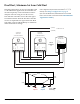
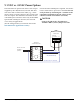
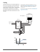
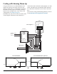
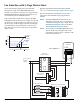
Table Of Contents
- Cover/Contents
- General Information (All Applications)
- Single-Zone Proportional Heating and Cooling Applications
- Pressure Dependent VAV Applications with MEP-4xx2
- Pressure Independent VAV Applications with CSP-4702
- Replacing a CSP-5001/5002
- Replacing a CEP-4xxx or CSP-40xx/42xx/44xx/46xx or CSE-484x
- Cooling or Heating
- Auto and Override (to Fully Open)
- Cooling with 3-Stage Reheat
- Cooling with 3-Stage Reheat and Night Setback/Setup
- Cooling with Heating Changeover
- Cooling with Heating Changeover and Electric Reheat
- Cooling with Heating Changeover and Hot Water Reheat
- Cooling with Hot Water Reheat
- Fan Induction with 2-Stage Electric Heat
- Dual Duct, Minimum Air from Cold Duct
- Pressure Independent VAV Applications with CSP-5001/5002
- Cooling or Heating
- Auto and Override (to Fully Closed or Fully Open)
- Cooling with 3-Stage Reheat
- Cooling with 3-Stage Reheat and Night Setback/Setup
- Cooling with Heating Changeover
- Cooling with Heating Changeover and Electric Reheat
- Cooling with Heating Changeover and Hot Water Reheat
- Cooling with Hot Water Reheat
- Fan Induction with 2-Stage Electric Heat
- Dual Duct, Minimum Air from Cold Duct
- Pressure Independent VAV and CAV Applications with CEP/CSP-4000 Series
- 9.1 VDC vs. 24 VAC Power Options
- Cooling
- Cooling with Morning Warm-Up
- Cooling with 3-Stage Reheat
- Cooling with Heating Changeover
- Cooling with Hot Water Reheat
- Fan Induction with 2-Stage Electric Heat
- Damper Tracking (Master/Slave)
- Dual Duct Heating and Cooling VAV
- Dual Duct Heat/Cool Constant Volume with Hot Deck Make-Up
- Barber Colman TP-81xx Thermostats Replacement Applications
- Index

Pressure Independent VAV Applications with CEP/CSP-4000 Series 47 CTE-5202 Applications Guide, AN0912A Rev. H
Cooling with 3-Stage Reheat
The application below uses an SSE-1000 series sen-
sor, an REE-4001/5001 relay module, and three 24
VAC contactors for three stages of reheat.
The transformer must supply a minimum of 10 VA
plus the requirements for the reheat contactor coils
(10 VA maximum per stage).
As the temperature drops below setpoint, the rst
stage of reheat begins. If the temperature continues
to drop, the second stage begins, and nally the
third stage if necessary.
Select Sequence 2 (from the
CTE-5202 SYSTEM menu).
See Change Conguration
on page 6. (This replaces a
CTE-1004 or a CTE-5002/5012
thermostat.)
If no Auxiliary Flow is desired,
set AO1 AUX to 0 in the
LIMITS menu.)
~
T
T
AI1
AO1
AO2
CTE-5202
Thermostat
24 VAC @ 40 VA
~
–
(Phase)
(Neutral)
1
2
3
7
6
5
4
3
2
1
8
9
10
11
12
13
14
CEP-4xxx
Controller-Actuator
SSE-1001/1002
Flow Sensor
REE-4001/5001
Relay Module
~
–
24 VAC
3 2 1
Stages
3-Stage Reheat
T
24 VAC Contactors
(10 VA Max. per Stage)
2
1
3
Load
Select Sequence 2
NOTE: Triac outputs on the
REE-4001/5001 are for
24 VAC loads only.
The phase side of the
transformer connects to
the “common” side of the
load (contactors).
NOTE: See also the REE-4001
Installation Guide
and/or REE-5001
Installation Guide.
2° F
Of Loop
10%
2° F
AO1 MAX
AUX
AO1 MIN
COLD AIR SEQUENCE
0 Volts
12 Volts
Temp. Increasing
Cooling
Setpoint
Heating
Setpoint
9.5 V
3.5 V
#3
#1
6.5 V
#2
Reheat
Stages
AO2 (RA)
AO1 (DA)