
Manual


CTE-5201 1 Installation and Operation Guide
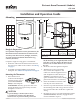
Mounting the Thermostat
1. Ifthethermostatis
lockedonthebackplate,
turnthetwohexscrews
(inthetwo outermost
holes)inthebackplate
CLOCKWISEuntilthey(just)clearthecover.
Swingthethermostatupandawayfromthe
backplatetoremoveit.
CAUTION
To prevent damage to the board, do not insert
a screwdriver into any holes other than the two
outermost holes. To prevent mounting screw heads
Installation and Operation Guide
Electronic Room Thermostat (Modular)
CTE-5201
Mounting
Rough-in Preparation
For optimum temperature sensor performance, the
thermostat must be mounted on an interior wall
and away from heat sources, sunlight, windows,
air vents, and air circulation obstructions (e.g.,
curtains, furniture).
Completerough-inwiringpriortoinstallation:
• Routethecablefromthethermostatlocationto
theactuatortowhichitwillconnect.SeeWiring
on page 2.
•
Ifneeded,installtheHMO-1161mounting
backplate.SeeAdditional Information on page 4.
from touching the circuit board in the thermostat, use
only the mounting screws supplied by KMC Controls.
Using other screws may damage the thermostat. Do
not turn screws in farther than necessary to remove
the cover.
2. Routethecablethroughthebackplate.
3. Withthehexscrewstowardthe
oor,fastenthebackplatetothe
outletboxwiththesuppliedscrews.
(Thebackplatemountsdirectlyon
vertical2x4inchboxes,butre-
quiresanHMO-1161wallmounting
plateforhorizontalor4x4boxes.)
4. Insertthemodularendofthecable
intothejackofthethermostat.
5. Placethetopofthethermostatoverthetopof
themountingbaseandswingitdownoverthe
hexscrewbrackets.Becarefulnottopinchthe
wiring.
6.
Backthehexscrewsoutofthebackplatebrackets
(counterclockwise) untiltheyengagethether-
mostatandholditinplace.
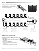
A
B
C
E F
RJ-12
Modular
Connector
D
Pin 6
Pin 1
Mounting 1
Rough-in Preparation 1
Mounting the Thermostat 1
Wiring 2
Modular to Modular (HSO-22xx Cable) 2
Modular to Leads (HSO-5012 Cable) 2
Operation 3
Turn On Backlight 3
Change Setpoint 3
Start Unoccupied Mode 3
Toggle Between °F and °C 3
Configuration 3
Changing Defaults 3
MAX 3
MIN 3
F/C 3
UNOCC 3
PROP 4
INT 4
Calibration (Temperature Offset) 4
Maintenance 4
Additional Information 4
Pin 1 and 6 Pin 2 and 5 Pin 3 Pin 4
N/C Common Supply
(14–19VDC)
Output
(2–10VDC)*
*0VDCduringUnoccupiedOmodewhentemperaturestays
above50°F
A
3.25
in.
83
mm
B
5.16
in.
116
mm
C
0.88
in.
22
mm
D
0.38
in.
10
mm
E
2.58
in.
66
mm
F
3.25
in.
83
mm