
Install Instructions


CSP-5001/5002 3 Installation Guide
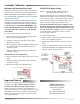
Controller Testing
Test the CSP-500x actuator’s motor operation:
1. Temporarily disconnect the thermostat reset
connection at Terminal “IN”.
2. Jumper “IN” terminal to the “16 VDC” terminal.
The green Open LED should illuminate. The shaft
drive hub should be rotating the damper open.
The damper should go to full open unless the
maximum limit was set at the CSP-500x, and then
the damper will only go to the maximum seing.
If the damper is rotating closed, the “Close”
jumpers must be changed. Refer to the Rotation
Setup section.
3. Jumper “IN” terminal to the “–” terminal. The
red Close LED should illuminate. The shaft
drive hub should be rotating the damper closed.
The damper should go to full closed unless the
minimum limit was set at the CSP-500x, and then
the damper will only go to the minimum seing.
If the damper is rotating open, the “Close”
jumpers must be changed. Refer to Rotation
Setup section.
Specifications
Supply Voltage 24 VAC (–15/+20%), 50/60 Hz,
Class 2 only (4 VA max.)
Output Supply 16 VDC (22 mA) to thermostat
Output Torque 50 in-lb. min., 70 in-lb. max.
Velocity Range 0 to 3300 fpm, dependent on
DP pickup, tubing size/length,
and connections
Signal Output 0 to 10 VDC (0 to 100% ow)
Signal Input 0 to 10 VDC (from thermostat)
Min./Max. Limits Adjustable, 0 to 100%
Angular Rotation 0° to 95° (both end stops
adjustable)
Stroke Time 18° per minute @ 60 Hz
Temperature Limits
Operating 32 to 120° F (0 to 49° C)
Shipping –40 to 140° F (–40 to 60° C)
More Information
For complete specica-
tions and list of acces-
sories, see the CSP-
5001/5002 Data Sheet on
the KMC web site.
For system testing
guidelines, sample
applications, and other
information about usage
with the CTE-5100 series
thermostats, see the
CSP-5001/5002 Applica-
tion Guide.
For information about
connections and usage
with newer CTE-5202
thermostats, see the
CTE-5202 Applications
Guide.
NOTE: For system testing guidelines and sample
applications, see the CSP-5001/5002
Application Guide.
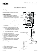
Rotation Setup
The CSP-5001 is factory-set for CCW to close. The
CSP-5002 is factory-set for CW to close. To reverse
the rotation direction of either controller model:
1. Remove the access door by pulling back on the
door’s tab and lifting upward.
2. Position both jumpers in either the CW or CCW
positions as needed. See the diagram.