
Application Guide

CSP-5001/5002 VAV Flow Controller-Actuators 3 Applications Guide, Rev. B
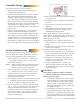
Controller, Sensor, and Thermostat Functions
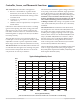
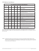
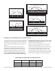
Typical Voltage/Velocity Chart
The chart below illustrates typical voltage versus ve-
locity using a CSP with a SSS-1002, single-point ow
sensor. Because this is a ow-through type sensor,
the tubing type will directly aect ow readings. To
maintain a close correlation with the factory cali-
bration, installations must use 24 inches of 1/4-inch
OD x 0.040 wall tubing without restrictions such
as ings or kinks. The voltage corresponds to both
“IN” (for desired ow) and “OUT” (for actual ow)
terminals.
The Thermostat: The CTE-5100 series thermostats
are designed for use with the CSP-5001/5002 Control-
lers and/or most other controls (using a half-wave
rectier power supply) requiring a 0–10 volt signal.
Some of these controls are: the REE-1000/5000 series
relays, the MEP-1200/5000 series actuators, and/or
the VEP series valves. Utilizing the MEP actuators,
the CTE-5100 allows seing minimum and maxi-
mum control points on the thermostat (see Thermo-
stat Checkout/Calibration Procedures).
Various thermostat models are available in this series
such as: single setpoint DA (5101), single setpoint
RA (5102), dual setpoint DA and RA (5103/5104), and
dual setpoint both DA (5105).
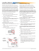
The Controller: The controller is designed to:
1. Receive a “desired ow” signal from the
thermostat (0–10 volts on terminal “IN”), or
the minimum and maximum seings on the
controller itself.
2. Compare it to “actual ow” (on terminals
“out” and “–”).
3. And drive the box open/closed, as required to
match airow.
LEDs show which direction the actuator is rotating
(green when opening, red when closing). The CSP-
5001 is factory-set to close counter-clockwise; the
CSP-5002, clockwise. However, rotation direction is
eld-changeable via jumper selection (see the Rota-
tion Setup section).
The CSP-5001 is factory set to measure airow of
0–3300 fpm at a 0–10 volt signal. This airow is eld
adjustable to match a specic requirement within
these ranges (see the Controller Calibration section).
The Flow Sensor: The CSP-5001/5002 controllers use
an onboard ow-through sensor utilizing twin plati-
num resistance temperature detectors to electroni-
cally measure air velocity in the duct.
0 500 1000 1500 2000 2500 3000 3500
Velocity (Feet Per Minute)
(CSP–5001 with the SSS–1002 in a 5-inch duct and 24 inches of 1/4-inch OD x 0.040 wall tubing)
0
1
2
3
4
12
11
10
9
8
7
6
5
Volts