
Applications Guide
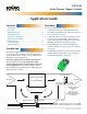
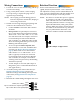
Table Of Contents

CSP-4702 Static Pressure (Bypass) Control 2 Application Guide, AN0114A Rev. A
Rotation Direction
Set the rotation direction to CW or CCW for the
“open” direction (instead of the “close” direction).
The CSP-4702 is factory-set for counterclockwise to
close. To reverse the direction (with the conduit cover
removed), move the jumper to the CW position.
NOTE: For about 15 seconds after power is applied,
no rotation occurs and one or both of the
LEDs will ash. The Close LED illuminates
(solid red) when the actuator is closing. The
Open LED illuminates (solid green) when
opening. When the actuator reaches the end
of rotation or the mechanical stop, the LED
may stay illuminated a brief time if the
called for condition remains unsatised.
Wiring Connections
1. Loosen the screw on the conduit ing and lift up
to remove the ing.
2. Using a utility knife or drill, cut the red plug
to accept wiring or replace the plug with an
application-specic ing.
NOTE: The red plug (or similar ing) protects
internal components from debris, helping to
ensure long actuator life.
3. Thread wires through the plugged opening and
connect to the terminal block as shown:
• Connect 24 VAC to the Phase and Common
terminals.
• Duct pressure can optionally be read across
the 1–5 VDC Output and Common terminals.
Then 1 VDC = 0" wc and 5 VDC = 2" wc, with
max. 10K ohm load. For example, connection
to an unused input of the nearest BACnet
VAV controller (e.g., KMC BAC-70xx) would
allow monitoring of the duct pressure by the
Building Automation System.
• To use an optional remote setpoint, MIN
limit should be set at 0 VDC and MAX limit
at 2 VDC (see Bypass Pressure Setpoint on
page 3). Then 2 VDC across that terminal
and Common = 0" wc and 10 VDC = 2" wc.
(This is typically not used, but connection
to an unused output of the nearest BACnet
VAV controller, for example, would allow
reseing of the duct pressure by the Building
Automation System.)
• 16 VDC Output is not used. (This output is
designed to power a CTE-5202 thermostat in
VAV applications.)
4. As needed, change the rotation direction (see
Rotation Direction on page 2) and set the
MIN ow seings after making the air pressure
connections (see Bypass Pressure Setpoint on
page 3).
5. Reinstall the conduit ing and tighten the screw.
CCW = Jumper on Upper 2 Pins
Phase
24 VAC (Class 2 Only)
Neutral
Opt. 2–10 VDC Remote Setpoint Signal (Input)
Opt. 1–5 VDC Air Pressure Signal (Output)