
Applications Guide
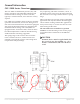
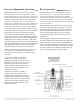
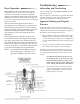
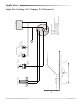
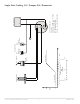
Table Of Contents

CSC–2000 Series Pneumatic VAV Reset Volume Controllers 6 Applications Guide
Pressure Independent Operation
Dierential pressure is sensed via a ∆P pickup
mounted upstream of the damper (VAV terminal
inlet). The ∆P pickup is a dual pressure pickup sens-
ing both high pressure and low pressure. The high
pressure is connected to the “X” port and the low
pressure is connected to the “Y” port. These two
pressures are compared across the static diaphragm,
which takes a position relative to the dierence of
the two pressures, the force of the LO limit adjust-
ment spring in the upper chamber, and the force of
the HI limit adjustment spring in the lower chamber.
Turning the “LO” knob clockwise (to increase)
relaxes the LO limit adjustment spring, placing a
lesser downward force on the diaphragm, reducing
the pressure at the “B” port, and increasing airow
through the VAV terminal. Turning the “HI” knob
adjustment spring counterclockwise positions the HI
limit stop downward, limiting the travel of the piston
cup, limiting the amount of reset, and seing the
maximum airow through the VAV terminal.
When the “HI” knob is turned fully counterclock-
wise, the HI limit will equal the LO limit, and
the controller will function as a constant volume
controller.
An increase in airow is sensed via
the increase in ∆P across the static
diaphragm, positioning the static dia-
phragm closer to the nozzle, increasing
the “B” port pressure to the actuator,
and decreasing airow until the static
diaphragm comes into balance at the
desired ∆P setpoint.
A decrease in airow is sensed via
the decrease in ∆P across the static
diaphragm, positioning the static dia-
phragm away from the nozzle, decreas-
ing the “B” port pressure to the actuator,
and increasing airow until the static
diaphragm comes into balance at the
desired ∆P setpoint.
Reset Operation
With sucient airow and a thermostat signal
connected to the “T” port of less than 8 psig, the
controller will position the actuator to regulate
airow at the LO limit seing. In this state, the static
diaphragm is balanced over the nozzle through the
forces of the opposing springs and forces of the high
and low pressures.
When the thermostat signal increases above 8 psig,
the piston cup will begin to position the reset lever
upward, increasing the force of the HI limit spring,
positioning the static diaphragm away from the
nozzle, opening the damper for greater airow,
and requiring a higher ∆P to rebalance the static
diaphragm.
The ∆P setpoint of the controller has been reset
upwards with the increasing thermostat signal. The
stroke of the piston cup is limited via the HI limit
knob. Lowering the HI limit will reduce the top end
of the reset span, narrowing the reset span. At each
new ∆P setpoint, as dictated by the thermostat sig-
nal, the static diaphragm will again balance.