
Install Instructions


CSC-2000 Series Reset Volume Controllers 4 Installation Guide© 2012 KMC Controls, Inc. 205-019-01R
KMC Controls, Inc.
19476 Industrial Drive
New Paris, IN 46553
574.831.5250
www.kmccontrols.com; info@kmccontrols.com
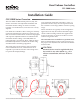
BEIGE Controllers (Direct Acting)
1. Check that there is 0 psi at the “T” Port.
2. Use a ow hood or “tee” a Magnehelic
®
(or equiv-
alent) dierential pressure gauge between the
controller and the ∆P pick-up.
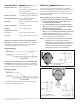
3. The “LO” ow seing limit (center knob) must
be set rst. Temporarily adjust the thermostat
for a branch pressure lower than the 8 psig reset
start point (minimum cooling); typically 6 psig or
less is best. Removing the thermostat branch line
would be another acceptable method. Adjust the
“LO” knob (center knob) clockwise to increase or
counterclockwise to decrease ∆P limit. Normally
one-half turn will cause a 0.1 ∆P change. Allow
for reaction time. Depending on actuator size and
position, timing will vary. To position an actua-
tor/damper from closed to open may take several
minutes.
NOTE: If the “LO” ow seing limit must be set at
“0” (zero minimum), do not turn the “LO”
knob fully counterclockwise. The knob will
adjust three to four full turns aer a zero
minimum is reached. Turning the “LO”
knob fully counterclockwise will result in
a negative reset condition. This means that
when the controller is beginning to reset
at 8 psig from the thermostat, it must rst
overcome the negative adjustment and will
not begin to reset until a higher thermostat
reset pressure is reached. This negative
reset will also reduce the eective range
of the controller by reducing the high end
and narrowing the reset span. If a zero
minimum is required, adjust the “LO” knob
until the controller just begins to crack the
damper open, then back-o one-fourth turn
and verify zero airow.
4. The “HI” ow seing limit (outer knob) must be
set aer the “LO”. Temporarily adjust the ther-
mostat for a branch pressure higher than the 13
psig reset stop point (maximum cooling); typically
17 psig or greater is best. Removing the thermo-
stat branch line and teeing-in to the main air line
would be another acceptable method. Adjust the
“HI” knob (outer knob) clockwise to increase or
counterclockwise to decrease ∆P limit. Nominally
one-half turn will cause a 0.1 ∆P change. Allow for
reaction time.
5. Recheck the “LO” and the “HI” seings at least
twice, verify seings, and ne tune each time if
necessary. This procedure will remove internal
component tensions and conrm seings.
6. Reconnect the thermostat branch line if necessary,
and adjust the thermostat to the desired room tem-
perature setpoint.
NOTE
: The “HI” adjustment limits the travel of
the reset mechanism. Therefore, the reset
span will be less than 5 psig, the upper limit
being less than 13 psig.
NOTE
: Always make adjustments in the same
plane/orientation as the one in which the
unit will operate.
More Information
For additional specications of particular models,
see the CSC-2000 Data Sheet (hp://bit.ly/PWVwol).
For principles of operation, troubleshooting, and
sample applications, see the CSC-2000 Applications
Guide (hp://bit.ly/RAWIzn).
Maintenance
No routine maintenance is required. Each compo-
nent is designed and manufactured for reliability
and performance. Careful installation and use will
ensure long-term dependability.
CAUTION
Pneumatic devices must be supplied with clean,
dry control air. Any other medium (e.g., oil
or moisture contamination) will result in the
device’s eventual failure.
(Scan QR code
to download
Applications
Guide.)