
Install Instructions


CSC-2000 Series Reset Volume Controllers 3 Installation Guide
Troubleshooting
The CSC-2000 series are position sensitive. Be sure
to mount the controller with the correct orientation.
See the Mounting section.
NOTE: If the controller is calibrated in a position
other than the nal mounting position, the
calibration (minimum and maximum ow
limits) will be o.
To minimize issues related to pressure, always use
3/8 in. tubing for the “X” and “Y” ports and keep
the tubing lengths as short as possible. If the sen-
sor has 1/4 in. ings, use 3/8 in. tubing and adapt-
ers at the sensor.
Some older style ow sensors may have restrictive
openings for the low pressure pickup. Replacement
of the ow sensor pickup may be necessary.
For additional troubleshooting information, see the
CSC-2000 Applications Guide.
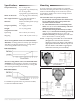
Connections
All Units
For all models of the CSC-2000 Series use 1/4 in. (6
mm) O.D. “FR” tubing for the following connections:
1. Connect the main air supply to port “M”.
2. Connect the actuator to port “B”.
3. Connect the thermostat to port “T”.
Beige Units
Use 3/8 in. O.D. “FR” tubing with a maximum
length of 24 in. to connect:
1. High pressure to port “X”.
2. Low pressure to port “Y”.
Gray Units
Use 3/8 in. O.D. “FR” tubing with a maximum
length of 24 in. to connect:
1. Low pressure to port “X”.
2. High pressure to port “Y”.
CAUTION
Pneumatic devices must be supplied with clean,
dry control air. Any other medium (e.g., oil or
moisture contamination) will cause the device
to fail.
Adjustments and Calibration
GRAY Controllers (Reverse Acting)
1. Check that there is 0 psi at the “T” Port.
2. Use a ow hood or “tee” a Magnehelic
®
(or
equivalent) dierential pressure gauge between
the controller and the ∆P pick-up.
3. The “HI” ow seing limit (center knob) must
be set rst. Temporarily adjust the thermostat
for a branch pressure lower than the 3 psig reset
start point (maximum cooling); typically 1 psig or
less is best. Removing the thermostat branch line
would be another acceptable method. Adjust the
“HI” knob (center knob) counterclockwise to in-
crease or clockwise to decrease ∆P limit. Normally
one-half turn will cause a 0.1 ∆P change. Allow
for reaction time. Depending on actuator size and
position, timing will vary. To position an actua-
tor/damper from closed to open may take several
minutes.
4. The “LO” ow seing limit must be set aer the
“HI”. Temporarily adjust the thermostat for a
branch pressure higher than the 8 psig reset stop
point (minimum cooling); typically 12 psig or
greater is best. Removing the thermostat branch
line and teeing-in to the main air line would be
another acceptable method. Adjust the “LO” knob
(outside knob) counterclockwise to increase or
clockwise to decrease ∆P limit. Normally one-half
turn will cause a 0.1 ∆P change. Allow for reaction
time.
5. Recheck the “HI” and the “LO” seings at least
twice, verify seings, and ne tune each time if
necessary. This procedure will remove internal
component tensions and conrm seings.
6. Reconnect the thermostat branch line if necessary,
and adjust the thermostat to the desired room
temperature setpoint.
NOTE
: The “LO” adjustment limits the travel of
the reset mechanism. Therefore, the reset
span will be less than 5 psig, the upper limit
being less than 8 psig.
NOTE
: Always make adjustments in the same
plane/orientation as the one in which the
unit will operate.
NOTE: For principles of operation and sample
applications, see the CSC-2000 Applications
Guide.