
Applications Guide
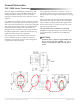

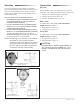
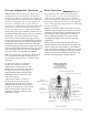
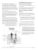
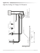
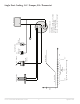
Table Of Contents

CSC–2000 Series Pneumatic VAV Reset Volume Controllers 4 Applications Guide
Connections
All Units
For all models of the CSC–2000 Series use 1/4 in. (6
mm) O.D. “FR” tubing for the following connections:
1. Connect the main air supply to port “M”.
2. Connect the actuator to port “B”.
3. Connect the thermostat to port “T”.
Beige Units
Use 3/8 in. O.D. “FR” tubing with a maximum
length of 24 in. to connect:
1. High pressure to port “X”.
2. Low pressure to port “Y”.
Gray Units
Use 3/8 in. O.D. “FR” tubing with a maximum
length of 24 in. to connect:
1. Low pressure to port “X”.
2. High pressure to port “Y”.
CAUTION
Pneumatic devices must be supplied with clean,
dry control air. Any other medium (e.g., oil or
moisture contamination) will cause the device
to fail.
Mounting
As close to the ow sensor pickup as is feasible,
fasten the mounting bracket to the mounting surface
with two self-threading screws in the two 3/16 in.
(5 mm) holes. (Make sure to leave enough room to
make connections.)
The CSC–2000 series are position sensitive:
The minimum and maximum ow limits must
be set (calibrated) in the same position the
controller will be mounted.
The CSC–2001/2002 (with 0–10 molded plastic
dials) must be mounted horizontally with dial
adjustment knobs facing up.
The CSC–2003 through CSC–2018 (no molded
dials) may be mounted horizontally (preferred),
with the adjustment knobs up or down, or
mounted vertically (the diaphragm inside must
be in a horizontal or vertical plane).
NOTE: If replacing a CSC–2001-22 or CSC–2002-22
(designed for vertical mount and now
obsolete), use the CSC–2001 or CSC–2002 as
appropriate and mount dials face up or use
the CSC–2003 or CSC–2004 as appropriate
and mount vertically or horizontally.
•
•
•
With 0–10 Molded Plastic Dial
(CSC–2001/2002)
Without
Molded Dial
(CSC–2003
through
CSC–2018)
Horizontal Mount, Knobs Up Only
Horizontal Mount
(Preferred, Knobs Up or Down)
Or Vertical Mount