
Applications Guide
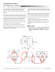
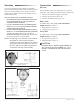
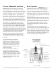
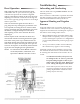
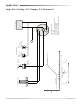
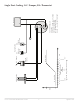
Table Of Contents

CSC–2000 Series Pneumatic VAV Reset Volume Controllers 8 Applications Guide
Reset Operation
With sucient airow and a thermostat signal
connected to the “T” port of less than 3 psig, the
controller will position the actuator to regulate
airow at the HI limit seing. In this state, the static
diaphragm is balanced over the nozzle through the
forces of the opposing springs and forces of the high
and low pressures.
When the thermostat signal increases above 3
psig, the piston cup will begin to position the reset
lever upward, increasing the force of the LO limit
spring, positioning the static diaphragm away from
the nozzle, closing the damper for less airow,
and requiring a lower ∆P to rebalance the static
diaphragm.
The ∆P setpoint of the controller has been reset
downwards with the increasing thermostat signal.
The stroke of the piston cup is limited via the LO
limit knob. Raising the LO limit will reduce the top
end of the reset span, narrowing the reset span. At
each new ∆P setpoint, as dictated by the thermostat
signal, the static diaphragm will again balance.
NOTE: For information about BEIGE controllers
see the Adjustments, Calibration, and
Operation of BEIGE Controllers section.
Troubleshooting
Subcooling and Overheating
The CSC-2000 series are position sensitive. See the
Mounting section.
If the controller is calibrated in a position other than
the nal mounting position, the calibration (mini-
mum and maximum ow limits) will be o.
Apparent Hunting and Negative
Pressure
In the CSC-2000 series of controller, under some
conditions such as low airows, unexpected signals
might be observed because of inadequate capacity of
the airow sensor tubing and/or sensor:
When calibrating these controllers and the VAV
damper blade is completely closed, it is possible
to see a small negative pressure on a Magnehelic
®
(or equivalent) dierential pressure gauge (up to
a –0.1).
At very low airows, under certain conditions,
the controller may appear as if it is hunting.
Although it might seem something is wrong with
the controller on the VAV box, the controller could
be working ne and external issues need to be cor-
rected.
To minimize this eect, always use 3/8
in. tubing for the “X” and “Y” ports and
keep the tubing lengths as short as pos-
sible. If the sensor has 1/4 in. ings, use
3/8 in. tubing and adapters at the sensor.
Some older style ow sensors may have
restrictive openings for the low pressure
pickup. Replacement of the ow sensor
pickup may be necessary.
•
•