
Applications Guide
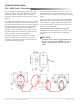
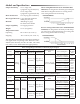
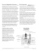
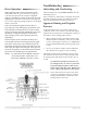
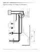
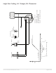
Table Of Contents

CSC–2000 Series Pneumatic VAV Reset Volume Controllers 7 Applications Guide
Adjustments, Calibration, and Operation of GRAY Controllers
Pressure Independent Operation
Dierential pressure is sensed via a ∆P pickup
mounted upstream of the damper (VAV terminal
inlet). The ∆P pickup is a dual pressure pickup
sensing both high pressure and low pressure. The
low pressure is connected to the “X” port and the
high pressure is connected to the “Y” port. These two
pressures are compared across the static diaphragm,
which takes a position relative to the dierence of the
two pressures, the force of the HI limit adjustment
spring in the upper chamber, and the force of the LO
limit adjustment spring in the lower chamber.
Turning the “HI” knob counterclockwise (to in-
crease) compresses the HI limit adjustment spring,
placing a greater downward force on the diaphragm,
increasing the pressure at the “B” port, and increas-
ing air through the VAV terminal. Turning the “LO”
knob adjustment spring counterclockwise positions
the LO limit stop downward, limiting the travel of
the piston cup, limiting the amount of reset, and set-
ting the minimum airow through the VAV terminal.
When the “LO” knob is turned fully counterclock-
wise, the LO limit will equal the HI limit, and
the controller will function as a constant volume
controller.
An increase in airow is sensed via the increase in
∆P across the static diaphragm, positioning the static
diaphragm away from the nozzle, decreasing the “B”
port pressure to the actuator, and decreasing airow
until the static diaphragm comes into balance at the
desired ∆P setpoint.
A decrease in airow is sensed via the decrease in
∆P across the static diaphragm, positioning the static
diaphragm closer to the nozzle, increasing the “B”
port pressure to the actuator, and increasing airow
until the static diaphragm comes into balance at the
desired ∆P setpoint.
Adjustments and Calibration
1. Check that there is 0 psi at the “T” Port.
2. Use a ow hood or “tee” a Magnehelic
®
(or
equivalent) dierential pressure gauge between
the controller and the ∆P pick-up.
3. The “HI” ow seing limit (center knob) must
be set rst. Temporarily adjust the thermostat
for a branch pressure lower than the 3 psig reset
start point (maximum cooling); typically 1 psig or
less is best. Removing the thermostat branch line
would be another acceptable method. Adjust the
“HI” knob (center knob) counterclockwise to in-
crease or clockwise to decrease ∆P limit. Normally
one-half turn will cause a 0.1 ∆P change. Allow
for reaction time. Depending on actuator size and
position, timing will vary. To position an actua-
tor/damper from closed to open may take several
minutes.
4. The “LO” ow seing limit must be set aer the
“HI”. Temporarily adjust the thermostat for a
branch pressure higher than the 8 psig reset stop
point (minimum cooling); typically 12 psig or
greater is best. Removing the thermostat branch
line and teeing-in to the main air line would be
another acceptable method. Adjust the “LO” knob
(outside knob) counterclockwise to increase or
clockwise to decrease ∆P limit. Normally one-half
turn will cause a 0.1 ∆P change. Allow for reaction
time.
5. Recheck the “HI” and the “LO” seings at least
twice, verify seings, and ne tune each time if
necessary. This procedure will remove internal
component tensions and conrm seings.
6. Reconnect the thermostat branch line if necessary,
and adjust the thermostat to the desired room
temperature setpoint.
NOTE: The “LO” adjustment limits the travel of
the reset mechanism. Therefore, the reset
span will be less than 5 psig, the upper limit
being less than 8 psig.
NOTE: Always make adjustments in the same
plane/orientation as the one in which the
unit will operate.
NOTE: No routine maintenance is required. Each
component is designed and manufactured
for reliability and performance. Careful
installation and use will ensure long-term
dependability.