
Install Instructions
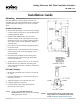

CEP-4000 Series 2 Installation Guide
Wiring
1. Connect the CEP to an SSE sensor:
A. Terminal 1 to sensor terminal 1.
B. Terminal 2 to sensor terminal 2.
C. Terminal 3 to sensor terminal 3.
2. Connect the CEP to a CTE thermostat:
A. Terminal 4 to thermostat terminal “–”.
B. Terminal 5 to thermostat terminal “+”.
C. Terminal 6 to thermostat terminal “T1” for
cooling (CTE-1001) or “T2” for heating air
ow(CTE-1002).
3. Connect the CEP to a 24 VAC, –15%/+20%, 50/60
Hz power source (disconnect the power to the
transformer while wiring the CEP):
A. Terminal 9 to the “–”common side of the
transformer.
B. Terminal 10 to the “~” phase side of the
transformer.
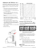
4. Optionally,theductairowcanbereadby
measuring the voltage on:
A. Terminal 2 (+) and 4 (–) for 9 to 18 VDC = 0 to
3000 fpm.
B. Terminal 7 (+) and 4 (–) for 1 to 5 VDC = 0 to
3000 fpm.
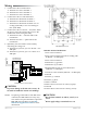
CEP-4000 Front View
CEP-4000 Basic Connections
CAUTION
To prevent damage to the SSE series sensors, do
not touch or handle the interior wire windings.
CAUTION
*Do not short terminals 12 and 14, 4 and 5, or 2
and 4.
†
Do not apply voltage to terminals 12 or 14.
NOTE: If replacing a CEP-1000 or CEP-3000 series
controller, the REE-1000 series relay may
also need to be replaced with the equivalent
REE-4000 series module. See the CEP-
4000 Series Application Guide for more
information.
CEP-4000 Terminal Denitions:
1. Flow sensor terminal 1
2.Flowsensorterminal2(liveowreadingwith
9–18 VDC = 0–3000 fpm)*
3. Flow sensor terminal 3
4. Thermostat (–) ground*
5. Thermostat (+) 9.1 VDC*
6.RequestedowfromT1orT2thermostat
(3–6 VDC = 0–3000 fpm)
7.Liveowsensorreadout(1–5 VDC = 0–3000 fpm)
8. Unused
9. 24 VAC (–) common
10. 24 VAC (~) phase
11. Motor common
12. Motor drive to increase air velocity (open)*
†
13. Unused
14. Motor drive to decrease air velocity (close)*
†