
User guide
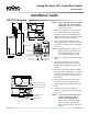
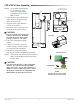
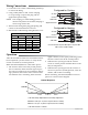
Table Of Contents
CEP-4703/4703V 3 Installation Guide
Wiring Connections
1. Loosen the screw on the conduit ing and lift up
to remove the ing.
2. Using a utility knife or drill, cut the red plug
to accept wiring or replace the plug with an
application-specic ing.
NOTE: The red plug (or similar ing) protects
internal components from debris, helping to
ensure long actuator life.
3. Thread wires through the plugged opening and
connect to the terminal block as shown.
4. Reinstall the conduit ing and tighten the screw.
Operation
After the mechanical and electrical installations have
been completed, cycle the actuator to verify the di-
rection of rotation for normal operation.
When the CEP-4703/4703V is connected to power:
1. The actuator drives to the fully closed position
(for two minutes). If the Override signal is pres-
ent (contact closed across two terminals), indicat-
ing system On, the actuator waits one more min-
ute and then starts controlling. If the Override
Setpoint Resistor*
°F Ohms °F Ohms
Chilled Water Hot Water
54 16.9K 94 6.98K
56 16.2K 96 6.65K
58 15.4K 98 6.34K
60 14.7K 100 6.04K
62 14.0K 102 5.90K
*1/4 Watt, 1%
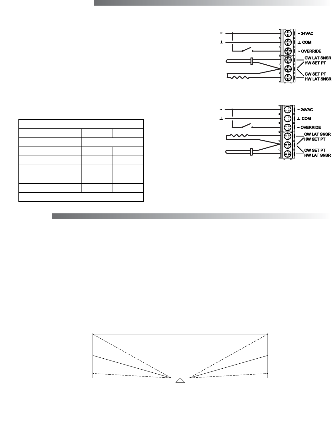
24 VAC
Contact Closed = System On; Open = System Off
CW to Close; CCW to Open
STE-1401
Setpoint Resistor
Configured for Cooling
Contact
24 VAC
STE-1401
Setpoint Resistor
Configured for Heating
Contact
100
% On Time
0
% On-Time Slope Adjustable Via Sensitivity Adjustment
Maximum = 30% per °F (faster response but less stable)
Minimum = 3% per °F (slower response but more stable)
% On-Time Period = 1 Minute
100
% On Time
0
CLOSE 1F SP 1F OPEN
Control Sequence
signal is absent (contact open), indicating system
O, the actuator waits in the closed position.
2. Whenever the system goes O, the actuator
stores its current position and then drives to the
fully closed position.
3. Whenever the system goes On, the actuator re-
turns to its previous (stored) position, waits one
minute, and resumes controlling.
When controlling, the CEP-4703/4703V control se-
quence is as shown in the diagram.