
Applications Guide
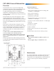
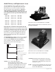
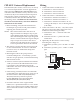
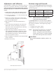
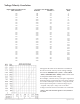
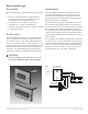
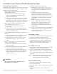
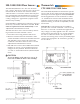
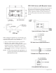
Table Of Contents
- CEP-4000 General Information
- SSE-1000/2000 Flow Sensors
- Thermostats
- VAV Single Duct Cooling/Heating Applications
- VAV Dual Duct Cooling/Heating Applications
- Index

CEP-4000 Series VAV Flow Controller-Actuators 4 Applications Guide
Wiring
1. Connect the CEP to an SSE sensor:
A. Terminal 1 to sensor terminal 1.
B. Terminal 2 to sensor terminal 2.
C. Terminal 3 to sensor terminal 3.
2. Connect the CEP to a CTE thermostat:
A. Terminal 4 to thermostat terminal “–”.
B. Terminal 5 to thermostat terminal “+”.
C. Terminal 6 to thermostat terminal “T1” for
cooling (CTE-1001) or “T2” for heating airow
(CTE-1002).
3. Connect the CEP to a 24 VAC, –15%/+20%, 50/60
Hz power source (disconnect the power to the
transformer while wiring the CEP):
A. Terminal 9 to the “–”common side of the
transformer.
B. Terminal 10 to the “~” phase side of the
transformer.
4. Optionally, the duct airow can be read by
measuring the voltage on:
A. Terminal 2 (+) and 4 (–) for 9–18 VDC = 0–3000
fpm.
B. Terminal 7 (+) and 4 (–) for 1–5 VDC = 0–3000
fpm.
CEP-4000 Basic Connections
CEP-4995 Universal Replacement
The CEP-4995 (100° rotation, CW to close, no sensor)
is a “universal replacement” for most applications
and will replace MOST CEP-1000/3000/4000 series
controllers. The CEP-4995 is factory-wired to rotate
clockwise (CW) to close and has internal stops that
limit actuator rotation to 100 degrees. No sensor
is included, and the unit must be calibrated with
the existing sensor. In addition to the instructions
elsewhere in this document, note these additional
instructions for this model.
1. Before installing, verify that the terminal unit
has damper stops in the closed position before
replacing the controller/actuator.
NOTE: Most VAV terminal units with 45 or 60
degree rotation have damper stops as part
of the damper blade design. Terminal units
that rotate 90 degrees have stops integrated
into the actuator and do not require damper
stops. If stops do not exist in the closed
position, the CEP-4995 will not work and a
correct replacement unit must be ordered.
2. The majority of CEP controllers are used on CW
to close VAV terminals. To convert a CEP-4995
to CCW to close, see the Rotation Setup and
Override section.
3. Mounting the CEP in the open position is
recommended practice. To manually cycle the
unit into an open position, see the Rotation Setup
and Override section.
4. If sensor resistance (measured between terminals
1 and 3) is between 100 and 400 ohms the sensor
is operational. The CEP-4995 must still be
calibrated to the sensor. See the Adjustments and
Calibration section.
5. If the existing controller/actuator is a CEP-1000
or CEP-3000 series, determine if any relays are on
the VAV terminal. REE-1001/1002/1006/1011/
1015/1017/1019 relays must be replaced
by their REE-4000 series equivalent (REE-
4001/4002/4006/4011/4015/4017/4019).
6. For future reference of the original model
number, use a permanent marker to cross out the
“4995” part of the new unit’s model number and
write in the model number of the old controller/
actuator.