
Applications Guide
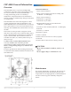
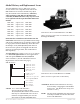
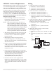
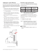
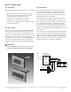
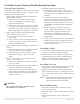
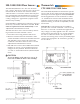
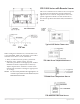
Table Of Contents
- CEP-4000 General Information
- SSE-1000/2000 Flow Sensors
- Thermostats
- VAV Single Duct Cooling/Heating Applications
- VAV Dual Duct Cooling/Heating Applications
- Index

CEP-4000 Series VAV Flow Controller-Actuators 10 Applications Guide
CEE-1000 Series with Remote Sensor
This series of thermostat is similar to the correspond-
ing model of CTE thermostat, but the CEE Series
requires use of a “remote” temperature sensor. For
specic application details on each model refer to
the relevant product Data Sheet and/or Installation
Guide.
CTE-1103
Typical CEE Series Thermostat
TTE-1001 Room Temperature Sensor
TTE-2001 Duct Temperature Sensor
TTE-5001/5011 Mini-Stat Sensor
When wiring these thermostats, 18 to 20 AWG wire
is recommended. Make sure all jumper wires under
terminal screws have a secure connection.
1. Verify 9.1 VDC between (+) and (–) terminals.
2. Measure “T(x)” output voltage. (Use the
calibration procedure on the appropriate model’s
Installation Guide to adjust limits if desired.)
Adjust setpoint above and below current room
temperature and observe changes in appropriate
“T” voltage.
NOTE: To more easily measure the appropriate “T”
or meter taps on the front of thermostat, use
HSO-5001 meter leads.